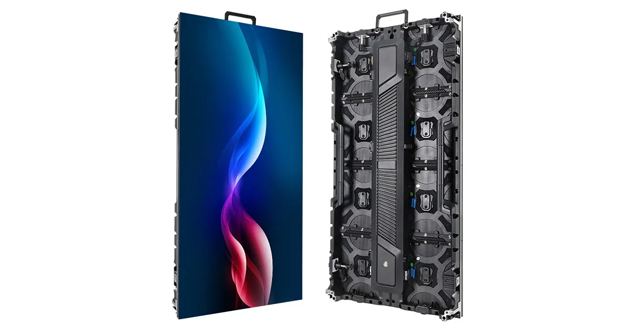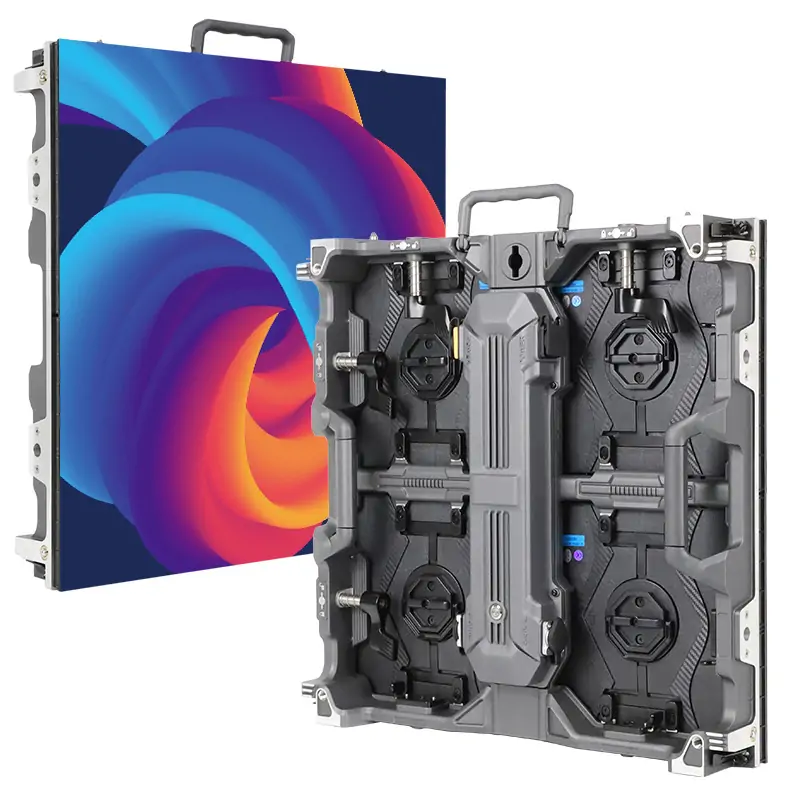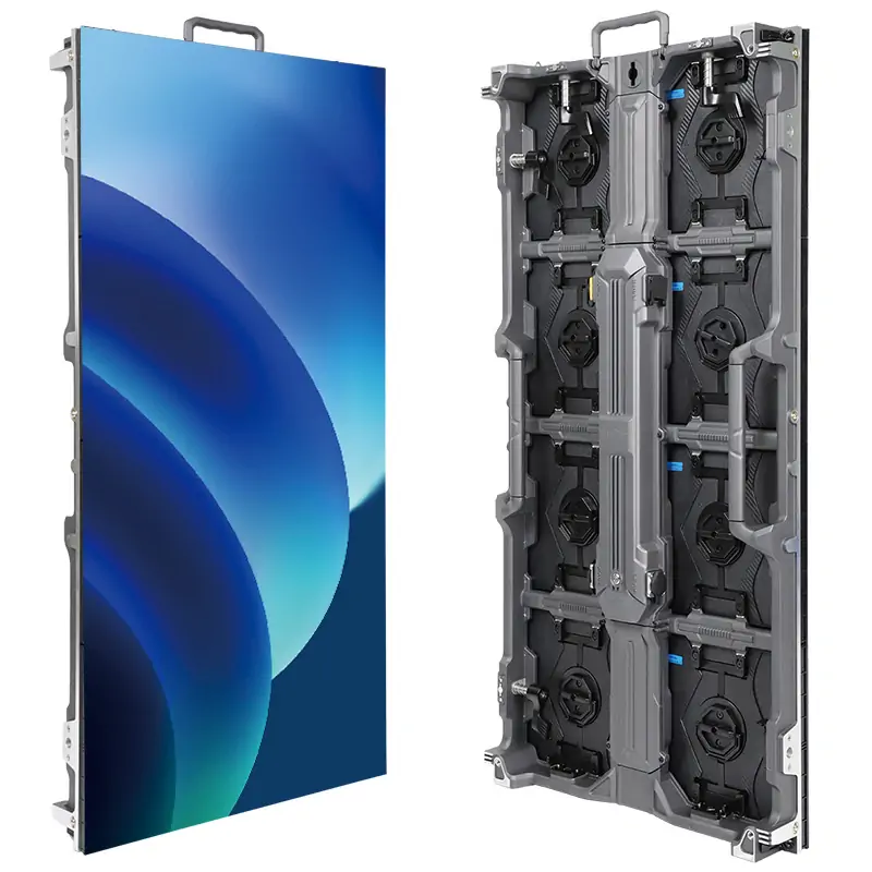
To set up the NovaStar VX1000, connect your source and LED cabinets, select the working mode, map the screen, configure input resolution and layers, then save and test the system. Use front-panel Quick Configuration for a regular cabinet grid and NovaLCT for detailed mapping. Configure redundancy separately and test each backup path before operation.
This guide covers the standard VX1000, a ten-port controller rated for up to 6.5 million pixels. Menu names follow NovaStar’s documentation; available settings can depend on firmware. The VX1000 Pro is a different model.
1. What You’re Setting Up — A Quick Hardware Tour for Novastar VX1000
Identify the controller, receiving cards and cabinet resolution before connecting software. NovaStar lists the VX1000 at 483.6 × 351.2 × 50.1 mm and 4 kg. Leave access for rear connections and ventilation, and mount it horizontally as instructed. Record the device firmware version and your cabinet supplier’s configuration file. See the official VX1000 specifications for dimensions and operating limits.
1.1 Rear Panel at a Glance
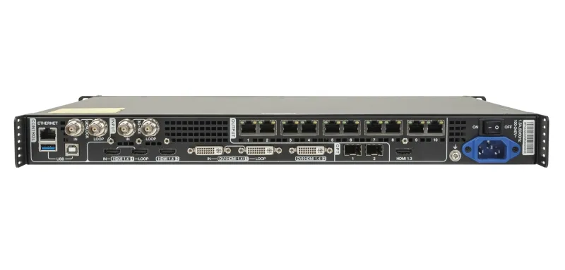
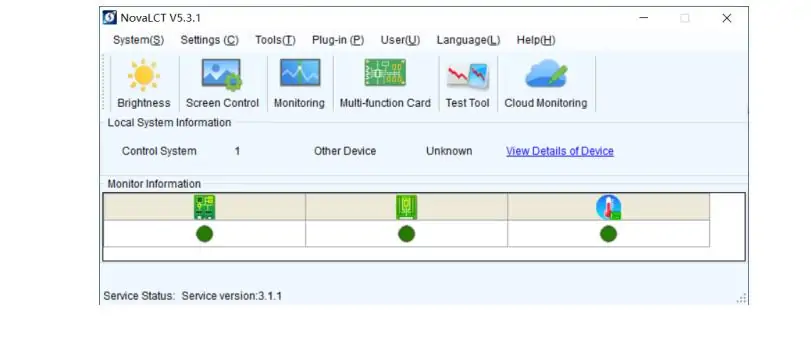
Video inputs: two HDMI 1.4 inputs, two DVI inputs compatible with HDMI 1.4, and one 3G-SDI input. HDMI 1 and DVI 1 provide loop outputs; SDI also has a loop output. HDMI/DVI accept up to 3840 × 1080 at 60 Hz or 3840 × 2160 at 30 Hz. SDI supports up to 1920 × 1080 at 60 Hz. These input limits differ from the LED output canvas limits.
LED outputs and fiber: ten Gigabit Ethernet ports send cabinet data. OPT 1 changes role with the connected equipment; OPT 2 copies or backs up the ten Ethernet outputs in Video Controller mode. Match optical modules, fiber type and connectors at both ends. A long cable run needs compatible optical hardware, not just a mode change.
Control and monitoring: use USB Type-B or the dedicated control ETHERNET connector for the PC. The numbered Ethernet outputs are for receiving cards. Genlock IN/LOOP handles external synchronization. HDMI output provides a 1920 × 1080 at 60 Hz monitoring feed in the normal monitoring configuration.
Audio output: Ethernet ports 1 and 2 support audio extraction through a compatible multifunction card. Select the audio source and output in Advanced Settings → Audio, and test the complete audio path. The connector descriptions are in NovaStar VX1000 user manual, chapter 2.
1.2 Front Panel Controls in 30 Seconds
Rotate the knob to select an item or change a value, then press it to confirm. ESC returns to the previous menu. Hold the knob and ESC together for at least three seconds to lock or unlock the front panel. Check the lock state before assuming the controls have stopped responding.
MAIN, PIP 1 and PIP 2 select layers. A steady blue layer button means the layer is open; flashing blue means it is being edited, and white means closed. Select a layer, then its input. SCALE fills the screen with the lowest-priority layer. PRESET opens preset operations, FREEZE holds the image, TEST opens test patterns, and FN is a configurable shortcut. Confirm that Freeze and fade-to-black are off before diagnosing missing video.
1.3 First Power-Up and Network Basics
After connecting the rated AC supply, check the LCD home screen for the input assigned to each layer, detected input resolution, screen resolution, brightness and port status. The LCD is a status display; use the HDMI monitoring output when you need a video preview. A missing input signal can mean a disconnected source, unsupported timing or a source that is not outputting video.
Before changing a previously used controller, note its current settings and save a configuration backup. Do not assume it is at factory defaults. After adjusting settings, NovaStar instructs you to wait at least five seconds before shutting the device down so parameters can be saved. Save receiving-card configuration explicitly as well, then test recovery during a planned restart. See NovaStar VX1000 user manual, chapters 4 and 5.
1.4 Getting the Novastar VX1000 Talking to Your PC
USB connection: connect the PC to the controller’s USB Type-B control port with a known-good data cable. Install a compatible NovaLCT release and its required driver, then check that the controller is detected. Our NovaStar software download guide explains the software options. The VX1000 uses AC power; USB is a control connection, not its power supply.
If detection fails, check power, cable seating, another PC USB port and the driver/device status in Windows. Test one change at a time. A damaged cable is possible, but there is no basis for treating ordinary USB Type-B cables as commonly charge-only or blaming the cable before checking the connection.
Ethernet connection: connect to the dedicated control ETHERNET port. Read the actual address on the LCD. In Communication Settings, select the network communication mode and configure IPv4 parameters as needed, then apply the change. Give the PC a different, unused address in the same subnet. For example, 192.168.0.100/24 can communicate with 192.168.0.10/24 on a suitable isolated setup network; these are examples, not guaranteed defaults or safe addresses on every venue network.
Check the selected PC adapter and link status if discovery fails. Keep a record of the controller address and avoid duplicate IPs. Use V-Can over Ethernet for the backup/restore and firmware workflows described later.
2. Three Working Modes of Novastar VX1000— When and How to Switch
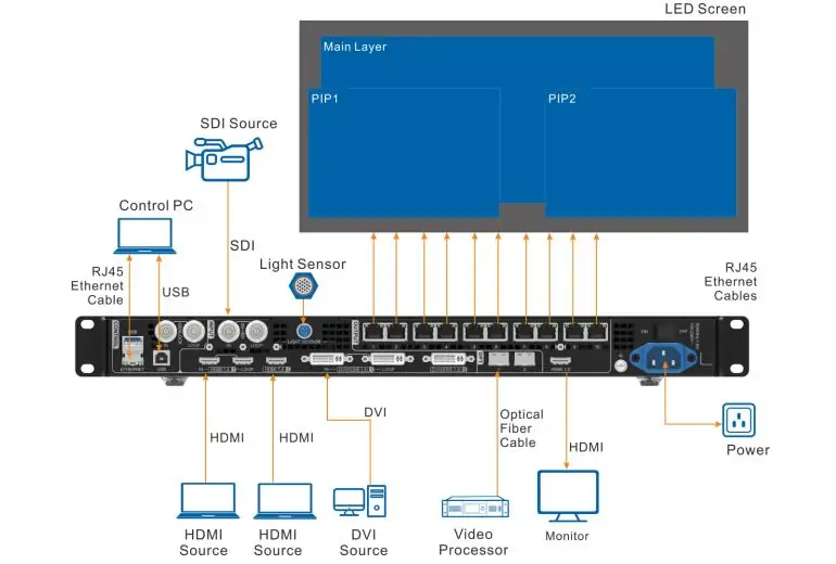
Choose the working mode before mapping and programming the show. Video Controller provides processing and layers; Fiber Converter receives optical data and outputs it to cabinets; Bypass sends the main image pixel-for-pixel without the normal video-processing functions. Switching modes changes which menus and features are available.
2.1 Video Controller Mode — Everyday Operation
Use Video Controller mode when you need scaling, input switching or picture-in-picture layouts. It combines video processing with LED sending, making it appropriate for presentations, event screens and installations with multiple source formats.
Open Menu → Working Mode and select Video Controller. Check the input assigned to the main layer, then build the screen mapping and layer layout. If layer or processing menus are missing, confirm the working mode first. Keep the HDMI monitoring output at its documented monitoring setting; changing it to a video-output configuration can affect the Ethernet output image.
2.2 Fiber Converter Mode — Long-Distance Signal Transport
In Fiber Converter mode, the VX1000 receives data through its optical inputs and sends it through the ten Ethernet outputs to the LED cabinets. This reverses the direction sometimes assumed from the term “converter”: it is the receiving unit at the screen end of this arrangement.
For a front-of-house-to-stage link, the upstream controller processes and sends the optical data; the stage-side VX1000 operates in Fiber Converter mode and feeds the cabinets. For example, a 200 m route requires optical modules and fiber rated for that route. Confirm model and optical compatibility before planning the link.
Set Menu → Working Mode → Fiber Converter on the receiving unit. In this mode, OPT 1 has priority; if its data is lost, OPT 2 can supply data, and OPT 1 resumes when its data returns. Only Working Mode, Communication Settings and Language menus remain available. Configure processing on the upstream controller. See NovaStar VX1000 user manual, sections 3 and 5.12 for the connection diagrams and mode behavior.
2.3 Bypass Mode — Lower Latency and Its Limits
Bypass mode displays the main input pixel-for-pixel and disables the two PIP layers. Use it when the source already contains the correct canvas and you do not need scaling or compositing. Check the source raster against the mapped screen before switching: content sized for a scaled layout may no longer fit.
NovaStar specifies input-to-receiving-card delay of 20 lines when both Bypass mode and Low Latency are enabled. This is a conditional device-path specification, not zero end-to-end camera latency. Cameras, converters, source timing and receiving-card behavior still affect the delay viewers see. See the VX1000 specifications, Low latency.
For image magnification (IMAG), test the complete camera-to-screen chain with the intended equipment and settings. Select Menu → Working Mode → Bypass, then Advanced Settings → Low Latency → On. Confirm the result on the actual screen rather than assuming a mode label guarantees acceptable delay.
Do not put a backup controller in Bypass simply because it is a spare. The primary and backup must reproduce the same intended image and have matching layer settings. A processed primary layout and a pixel-for-pixel backup can produce different pictures even when the backup cables are connected correctly.
3. Screen Configuration — Quick Setup vs NovaLCT
Map the screen before adjusting presets or testing redundancy. Prepare a drawing with cabinet rows, columns, pixel dimensions, cable order and the port serving each chain. Calculate total pixels and the load on each output. A screen that fits the controller’s overall capacity can still overload an individual port.
3.1 Quick Configuration via Front Panel
Quick Configuration is suitable for a regular screen made from cabinets of the same resolution, with a supported wiring pattern. Confirm that the receiving cards already have the correct cabinet parameters. It is not a substitute for a cabinet supplier’s receiving-card configuration.
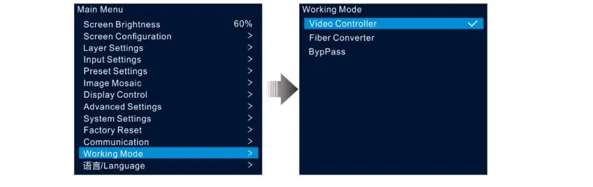
Go to Menu → Screen Configuration → Quick Configuration. Set Cabinet Row Qty, Cabinet Column Qty, Port 1 Cabinet Qty and Data Flow (Front View). View the wiring direction from the front of the screen and start the physical connection at Ethernet port 1.
The manual requires cabinet quantities in descending order: port 1 ≥ port 2 ≥ … ≥ port 10. Each port’s quantity must be an integer multiple of the screen’s cabinet row or column count. Port 1’s cabinets must not exceed 650,000 pixels. If your actual wiring does not meet these conditions, use detailed configuration instead of forcing it into a quick-setup pattern.
Confirm the values, then check a grid or numbered test image for repetition, missing cabinets and incorrect orientation. A solid color can reveal a dark cabinet but will not reliably expose a swapped mapping order. See NovaStar VX1000 user manual, section 5.2.1.
3.2 Full Configuration via NovaLCT
Use NovaLCT for layouts that need individual port or cabinet mapping, irregular shapes, or detailed receiving-card settings. Mixed cabinets require confirmed compatibility and appropriate parameters for each type; software does not make arbitrary cabinets interchangeable.
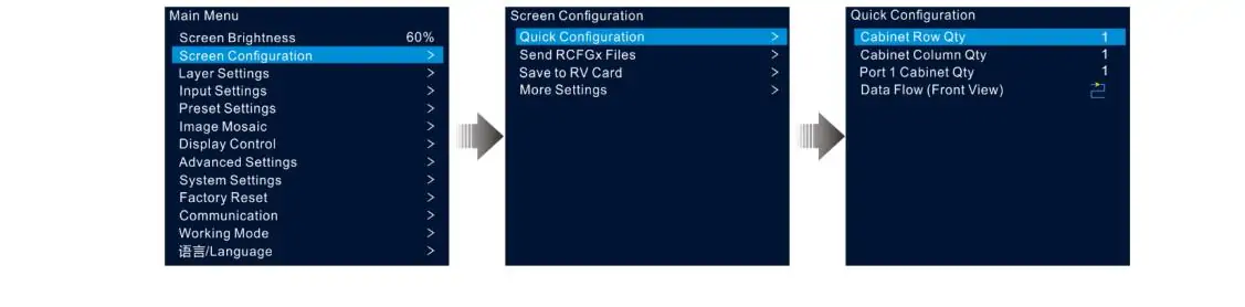
1. Connect and identify. Use a compatible NovaLCT version, select the detected control system and enter the Advanced Synchronous System User workflow. Record the existing configuration before sending new parameters. The screenshot below illustrates an older interface; labels can vary by release.
2. Load cabinet parameters. Obtain the correct .rcfgx file from the cabinet supplier, or read and save parameters from a known-working compatible installation. Verify cabinet resolution, scan configuration and receiving-card model. Do not send an unverified file to the whole wall. The VX1000 manual also documents Tools → Controller Cabinet Configuration File Import, followed by Save the Change to HW, for storing a cabinet file on the controller.
3. Map the connections. In Screen Configuration, use Screen Connection to assign receiving cards to the correct sending port and physical cable order. Enter the actual cabinet dimensions and offsets. Where supported, Mapping displays port and receiving-card identification on the screen so you can compare the logical layout with the wiring. It is an identification aid, not an automatic replacement for checking the cable route.
4. Send, verify and save. Send the settings to hardware, inspect the displayed image, and use the relevant save operation to retain the configuration. Screen Configuration → Save to RV Card saves the configuration sent to receiving cards against power loss. Keep the screen-connection file and a device backup on the PC as well; saving receiving-card parameters alone is not a complete replacement-controller recovery plan. See NovaStar VX1000 user manual, sections 5.2.2–5.2.5 and chapter 7.
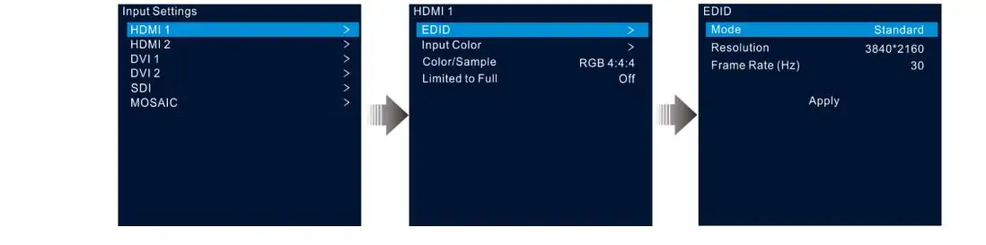
3.3 Input Resolution and EDID Setup
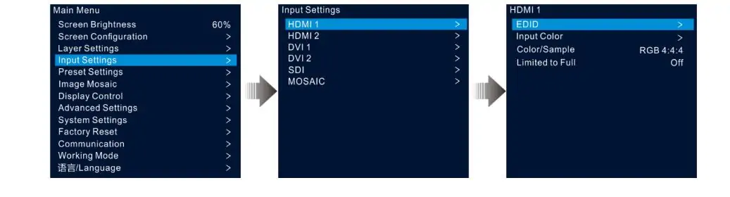
EDID tells a source which display timings the controller advertises. For a supported HDMI/DVI input, open Input Settings, select the connector and configure its resolution using Standard or Custom settings. Apply the change, then check the actual input timing shown by the controller and the output selected on the source PC.
The source resolution, layer dimensions and LED canvas are related but different settings. A custom media-server canvas must fit the input connector’s supported timing limits. SDI input resolution is determined by the incoming signal rather than this EDID adjustment.
If content does not fill the indoor LED display screen, compare the source aspect ratio, crop, layer size and screen mapping. Black bars may be embedded in the content or introduced by aspect-ratio handling. Check those separately from EDID; changing EDID alone does not guarantee a correctly filled image.
4. Backup and Redundancy of Novastar VX1000
The NovaStar VX1000 offers input, Ethernet-port, optical-output and device backup options. Choose the protection your installation needs and configure each relevant path. Enabling one option does not create the cables, independent sources or secondary controller required by another. Configuration-file backup is a separate recovery task.
4.1 The Four Levels of Backup
Input backup: pair sources of the same connector type under Advanced Settings → Input Backup and enable the function. A valid backup signal can replace a lost active input. If the original source recovers while the backup remains valid, the layer does not automatically return to it. A frozen picture that still has a valid signal may require operator intervention.
Ethernet port backup: connect the redundant cabinet paths and configure primary/backup port relationships in NovaLCT. The manual uses Screen Configuration → Sending Card → Redundancy. Record every port pair and check the receiving-card chain at both ends.
OPT output backup: Advanced Settings → OPT 2 Mode → Backup assigns the optical output a backup role. It requires a compatible fiber converter, the documented return connections and correct port relationships. Selecting Backup without that physical path provides no protection.
Device backup: use two controllers receiving the required source signal, with matching layers and corresponding cabinet loads. This can protect against loss of the primary controller. Consider shared source distribution and power as possible common failure points. See NovaStar VX1000 user manual, sections 5.8.1, 5.8.2 and 5.8.9.
4.2 Configuring Device Backup Step by Step
First, draw both signal paths and confirm how each controller receives the program source. A distribution amplifier can feed both units. If using a loop output, test whether the downstream feed remains available when the upstream device loses power; do not assume it does.
Connect the primary and backup to the receiving-card chains according to NovaStar’s device-backup diagram. The cabinet count on each corresponding Ethernet port must match, and the data flow must be reversed. “Reversed” refers to the chain’s actual cable order, which may snake across rows; it is not always simply left-to-right versus right-to-left.
On the primary, open Advanced Settings → Device Backup and select Primary. Set the second unit to Backup. Match the layer status, input assignments, sizes, positions, crop and other layer properties so either device can reproduce the same picture.
Check each port’s status and test the system rather than relying on an assumed pairing icon. Keep a port map beside the rack and record the settings on both units. If failover produces a different layout, review the source and layer configuration as well as cabinet counts and cable direction.
4.3 Testing Your Backup Before Doors Open
Run failure tests during a maintenance or setup window when interruption is acceptable. Use recognizable moving content and a grid so you can detect a frozen image, incorrect mapping or missing cabinets. Record the result and recovery behavior after each test.
Controller failure: remove power from the primary in a controlled test and verify the backup image across the entire indoor LED wall. Restore power and confirm the intended operating state. A failed test can involve source distribution, mapping, port relationships or layer settings; it is not limited to two possible causes.
Input failure: disconnect the active input and verify that its paired backup is valid and selected. Restore the source and check which input remains active, since input backup does not necessarily revert automatically.
Output-path failure: disconnect one active Ethernet path and inspect the affected chain. If optical redundancy is installed, test that path separately. Restore each connection before moving to the next test. Repeat relevant checks after firmware, mapping, source or cable changes; no fixed five-minute estimate suits every installation.
4.4 OPT 2 Mode — Copy vs Backup
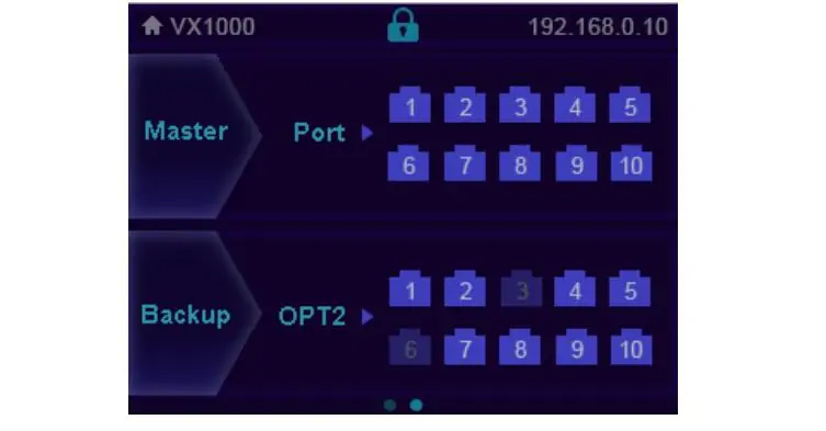
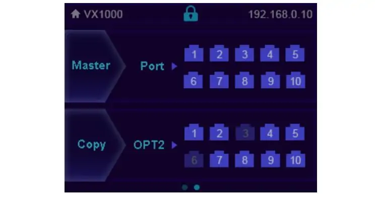
Copy mode sends a copy of the ten Ethernet outputs through OPT 2 to the remote fiber converter. The converter follows the same data-flow direction. Use this for optical distribution to cabinets through the converter, with fiber and modules matched to the link.
Backup mode uses OPT 2 for the documented redundant output arrangement. Connect the converter to the cabinet chains and verify the primary-to-backup Ethernet port relationships shown in NovaStar’s diagram. It is not an automatic alternative route through any available fiber cable.
The images below and above show port-status screens. Master/Port identifies controller Ethernet status; the OPT 2 area identifies the connected converter’s port status. Confirm the selected mode in Advanced Settings → OPT 2 Mode and test the actual path. The connection diagrams are in NovaStar VX1000 user manual, section 5.8.9.
5. Layers, Presets, and Input Settings of Novastar VX1000
After mapping and backup tests, configure the operator’s layouts. Keep source selection, layer geometry and preset naming consistent with the show plan. Test these settings with the actual content, especially small text, cropped camera feeds and graphics near screen edges.
5.1 Building Your Layer Layout
The VX1000 supports a main layer and two PIP layers in Video Controller mode. Build text or logo graphics in your source content or a suitable layer; do not assume a separate onboard OSD graphics generator is available. Using a mosaic source on the main layer prevents opening the two PIP layers.
Press MAIN, PIP 1 or PIP 2, then select its input. In Layer Settings, adjust size, position, input crop and opacity. Confirm the image after each adjustment. A layer at 0% opacity is transparent, so an apparently missing source may simply have an opacity or stacking issue.
Priority 1 is at the bottom; priority 3 is on top. Higher values place the layer in front. SCALE fills the screen with the bottom, lowest-priority layer; it does not bring that layer to the front or remove PIPs. Keep a background program layer below the PIPs when that is the intended composition. See NovaStar VX1000 user manual, section 5.3.
5.2 Preset Workflow
The VX1000 stores ten user-defined presets containing layer-related settings. Plan the layouts you need, such as full-screen presentation, camera with slides, interval content and a simple fallback source. Use descriptive names and a short cue list; V-Can supports renaming presets.
To save, press PRESET or open Preset Settings, choose a slot, press the knob to open its operations, select Save and confirm. Check that the slot reads Saved. To recall it, select the saved slot, open its operations and choose Load; its status changes to In Use. Selecting a slot alone is not the complete save or load operation.
Test each recalled preset with live sources. Presets retain layer status, input, size, position, priority, cropping, opacity and input-source color; they are not a full system backup. Keep the exported device configuration separately.
Do not confuse preset recall with input-transition settings. Display Control offers Fade or Cut for main-layer input switching and a fade-to-black function. Check their behavior before show operation instead of assuming every switch is an instant cut. See NovaStar VX1000 user manual, sections 5.5 and 5.7.
5.3 Input Settings Quick Reference
Input Settings includes resolution/EDID and source-color controls. Start from known settings, verify the detected timing, and use a test image to check black level, white level and color before making adjustments. Confirm input color range and source output settings when dark or bright details appear clipped.
HDCP is under Advanced Settings → Input HDCP. NovaStar instructs users to enable it when processing an HDCP-encrypted input. Turning it off is not a general cure for a black screen and can prevent protected material from displaying. Check source output, supported resolution and refresh rate, cable integrity, input assignment, layer opacity, Freeze and fade-to-black first.
Use a known-good unprotected test source to isolate a signal-path problem. Change one setting at a time and record the result so a temporary troubleshooting change does not become an unexplained show setting. See NovaStar VX1000 user manual, sections 5.4 and 5.8.6.
6. Field Tips That Save You on Show Day
Use the following checklist to make a validated setup easier to operate and recover. These are practical workflow recommendations; they do not replace the cabinet supplier’s parameters or NovaStar’s connection requirements.
Label the preset cue list. Keep each slot number, name and expected source beside the controller without covering vents. Verify the fallback layout during rehearsal. A readable cue sheet is more useful than remembering which numbered slot contains the simplest working picture.
Keep a tested recovery package. After the failover checks in section 4, export the device configuration through V-Can → System → Backup over Ethernet. Keep that file with the NovaLCT mapping, cabinet files, port diagram and firmware version. Configuration export supports restoration; it does not perform live failover. Test recovery during planned downtime because restoring a device restarts it.
Schedule firmware changes during maintenance. Use firmware intended for the exact VX1000 model and follow NovaStar’s update procedure in V-Can. Allow time to recheck inputs, mapping, layers and backup afterward. Retain the previous configuration and release information, but confirm downgrade compatibility with the supplier rather than assuming any older firmware can be restored from USB.
Label both ends of every cable. Include controller identity, port number and cabinet-chain destination, with distinct labels for primary and backup paths. Keep the labels consistent with the saved wiring diagram. This makes it easier to locate a failed chain without disturbing adjacent working connections.
Prepare a known-good control connection. Carry a tested USB data cable and Ethernet cable, keep the supported software installer available, and record the PC’s network settings. If detection fails, compare power, link status, adapter selection and drivers before changing screen parameters. Control connectivity and LED output mapping are separate troubleshooting steps.
7. FAQs
8. Conclusion
A reliable NovaStar VX1000 setup starts with the correct cabinet parameters, a verified port map and a working mode suited to the source. Save the configuration, check every preset and test the backup paths you actually installed. Keep the official VX1000 manual and specifications with the project files for connection diagrams and model-specific limits.
When troubleshooting, separate the problem into source input, video processing, cabinet mapping and control connectivity. Check one stage at a time using known-good content and saved settings. This avoids changing a working part of the system while trying to solve a different fault.
If your project also uses a NovaStar multimedia player for scheduled content, see our ViPlex Express content-publishing guide. That is a separate player workflow; the VX1000 setup described here receives and processes video from connected sources.
 12 LED Screen Manufacturers and Suppliers Serving Russia
 Novastar VX600 Pro vs VX600: What's Actually Different
Related Posts


Fill In Your Needs In Detail
Fill in the screen usage scene and size you need in “Content”.You will get a quote.