A surface-mounted device LED (SMD LED) is a light-emitting diode package soldered directly to pads on a printed circuit board. It describes the mounting format, not one brightness, color, voltage, or display technology.
SMD LEDs serve as indicators, lighting sources, LCD backlights, and RGB pixels in direct-view LED screens. A white lighting LED and an RGB display package can both be SMD devices while having very different electrical, optical, and thermal requirements.
This guide explains package construction, size codes, applications, and selection. Start with the exact manufacturer part number and datasheet: a label such as 5050 identifies a package family or footprint, but does not establish its color, power rating, pinout, or suitability for your project.
1. What Is a Surface-Mounted Device LED?
An SMD LED has external solder contacts that attach to the PCB surface. The semiconductor die is housed inside the package; it is not normally a bare chip placed directly onto the display board.
SMD and through-hole describe different mounting methods. Through-hole LEDs use leads inserted through PCB holes. SMD packages use surface pads and support automated placement and reflow soldering. Neither mounting method alone guarantees higher efficiency, longer life, or better heat dissipation.
1.1 SMD LED Technology
A package combines the light-emitting die, electrical connections, supporting structure, and optical protection. The following parts describe common constructions; ceramic, chip-scale, and flip-chip designs may use different materials or omit individual features.
1.2 LED Chip
The semiconductor die emits light when current passes through its junction. Common material systems include:
- Indium gallium nitride (InGaN): Used for many blue and green emitters. White light usually requires wavelength conversion or color mixing.
- Aluminum gallium indium phosphide (AlInGaP): Used for many red, amber, and yellow emitters.
For a specific blue example, Kingbright’s APG1608QBC/G datasheet identifies an InGaN source.
1.3 LED Frame
Many packages use a metal lead frame; others use a different substrate. Its functions include:
- Supporting electrical connections between the die and external contacts.
- Providing a heat-transfer path toward the solder joints and PCB, sometimes through a dedicated thermal pad.
The actual thermal path depends on the package construction.
1.4 Bond Wires
Wire-bonded packages use fine wires to connect die contacts to the package terminals. Gold is one possible material, not a universal requirement. Some flip-chip designs omit wire bonds: ams OSRAM’s OSLON PURE 1010 application note documents a non-wire-bonded example.
1.5 Encapsulating Silicone
Silicone encapsulation can protect the die and help control light distribution. Packages may use a dome, flat surface, epoxy, or another optical structure. Silicone is not immune to damage or aging: follow the manufacturer’s handling, cleaning, temperature, and material-compatibility guidance.
1.6 The Phosphor Layer (for white LEDs)
Many white LEDs combine a blue emitter with phosphors that convert some light into longer wavelengths. The combined spectrum appears white; phosphor selection affects color temperature and color rendering. RGB LEDs can also mix colors to produce white, as explained in the US Department of Energy’s LED basics.
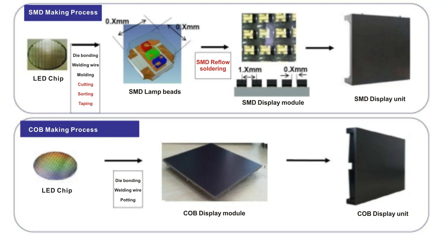
The process graphic below contrasts separately packaged SMD emitters, reflowed onto a display PCB, with COB dies assembled directly on a common substrate. It is a simplified illustration; not every design uses bond wires.
2. Key Features & Advantages Of SMD LED Technology
SMD packaging supports compact assemblies and repeatable manufacturing. The benefits depend on the selected component, PCB, driver, optics, and operating conditions.
2.1 Surface Mount Designing
Surface mounting supports pick-and-place assembly and reflow soldering. It can reduce manual assembly work, but does not automatically reduce the number of circuit components. Drivers, current limiting, protection, and thermal design still need to match the application.
2.2 Compact Size
Small packages allow closely spaced emitters. In direct-view displays, resolution depends on pixel pitch and screen dimensions, not simply the package label. Pixel pitch is the distance between adjacent pixel centers; it is different from the LED package’s physical width.
2.3 Integrated Lens and Encapsulant
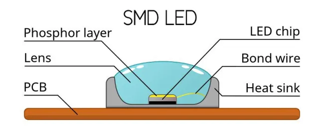
The lens or encapsulant protects internal parts and shapes the output, but cannot prevent all physical damage. The diagram below shows a white LED with a chip, phosphor, bond wire, optical cover, thermal structure, and PCB. It represents one construction, not every SMD LED.
2.4 Wide Viewing Angle
Viewing angle varies by part and by the manufacturer’s measurement definition. For example, Kingbright specifies a 130-degree full viewing angle at half intensity for APG1608QBC/G. A component’s angular intensity curve does not guarantee uniform color across a complete display, and diffusers or secondary optics may still be needed.
2.5 Multiple-Chip Configuration
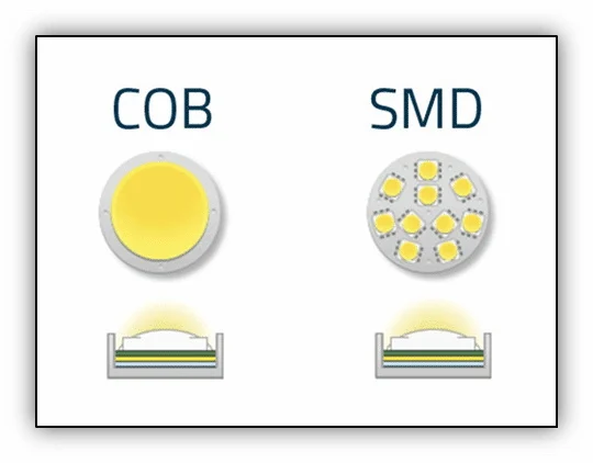
Multi-die packages can contain RGB emitters, multiple white emitters, or other combinations. Cree LED’s CLY6D-FKC is a three-color SMD example intended for full-color signage. The illustration below instead compares a COB lighting source with a board containing several separate SMD emitters; it does not show multiple chips inside one SMD package.
2.6 Solid-State Construction
LEDs generate light without moving parts, but solder joints, encapsulants, and internal connections can still be damaged by impact, board flex, or thermal cycling. Reliability requires appropriate assembly and operating conditions.
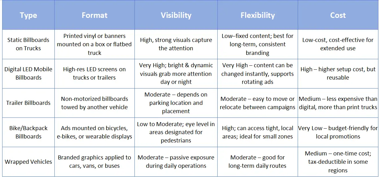
Context for the retained graphic below: it compares mobile advertising formats, not SMD components: printed truck panels, digital LED trucks or trailers, towed billboards, bicycle/backpack displays, and wrapped vehicles. Digital content can be changed electronically; printed graphics require physical replacement. Its visibility, cost rankings, and tax statement are general claims, not verified specifications or pricing for an SMD screen.
3. Applications Of SMD LED
Choose the emitter for the task. An indicator, white backlight, RGB display pixel, and infrared source are different products even when each uses surface mounting.
3.1 Consumer Electronics
Smartphones:
- Status indicators on models that include them.
- Camera flash or torch lighting.
- Backlighting on LCD-equipped models; OLED screens do not need an LED backlight.
Televisions and monitors: LED-backlit LCD products, including many QLED models, use LEDs as a light source behind the LCD. This differs from a direct-view LED video wall.
Wearables:
- Indicators.
- Backlights where an LCD design requires them.
- Emitters for selected optical-sensing functions in fitness trackers.
Gaming: RGB lighting can appear in:
- Keyboards.
- Mice.
- Consoles.
- PC components.
3.2 Specialized Applications
Horticulture: Manufacturers offer spectral options for growing applications; Lumileds’ horticulture range includes purpose-designed packages.
Medical equipment: Specialized emitters may be used in:
- Surgical illumination.
- Examination lights.
- Purpose-built phototherapy equipment.
UV curing: Suitable ultraviolet sources can cure compatible:
- Inks.
- Resins.
- Adhesives.
Infrared applications:
- Camera illumination.
- Remote-control signaling.
Wavelength, output, and device requirements are application-specific; ordinary RGB display LEDs are not substitutes. Lumileds’ specialty overview distinguishes camera-flash, display, IR, and UV products.
4. Understanding SMD LED Naming (The Number Code)
SMD LED size codes are useful clues, but they are not a complete specification.
Many lighting package names express nominal dimensions in tenths of a millimeter. Other families use inch-based codes. Always check the package drawing and recommended solder-pad pattern; matching the outer dimensions does not guarantee a compatible footprint or polarity.
Common metric examples are:
- 3528: Approximately 3.5 × 2.8 mm.
- 5050: Approximately 5.0 × 5.0 mm.
- 2016: Approximately 2.0 × 1.6 mm.
By contrast, an inch-based 0603 package is approximately 1.6 × 0.8 mm, as shown in Kingbright’s 0603 range. Do not read it as 0.6 × 0.3 mm without checking the naming system.
5. Categories and Types of SMD LEDs
Categories overlap: a top-emitting package can also be high power or contain multiple dies. Emission direction, package material, dimensions, and electrical rating describe different properties. COB is included below for comparison with packaged SMD devices.
5.1 Standard LED Lamps
Standard top-emitting LEDs direct light away from the board. Some use a plastic leaded chip carrier (PLCC); others use chip-style or ceramic constructions. A flat optical surface is possible, so a visible dome is not required for a component to be an SMD LED.
“Top-view” describes the main emission direction relative to the PCB. Use the datasheet’s radiation pattern to assess angular output rather than assuming all top-view packages produce the same beam.
Common sizes and uses:
- 0201/0402/0603: Small indicator families; confirm whether the supplier uses inch-based codes.
- 0805/1206: Larger chip-style indicators that can be easier to handle during prototyping.
- 3528: Used in indicator and lighting products; ratings vary.
- 5050: Can be RGB or white. Lumileds’ LUXEON 5050 is a white-light product family, so the code does not mean “three RGB chips.”
- 5630: A lighting footprint; compare actual output and current ratings.
- 5730: Another footprint, not proof of better efficacy than 5630.
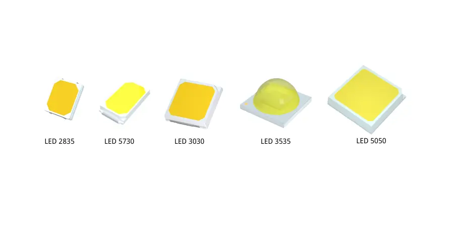
The retained illustration labels 2835, 5730, 3030, 3535, and 5050 packages; it is not a scale drawing or performance ranking.
5.2 Side-View LEDs (Side-Emitting)
Side-emitting LEDs direct their main output approximately parallel to the PCB, rather than perpendicular to it. Their optical geometry suits edge lighting and constrained assemblies. The external package does not establish the exact orientation of the internal die.
Direction of light:
- Along the board plane, approximately 90 degrees from its normal.
- Useful for coupling light into an edge-lit light guide.
Sizes and types:
- Dimensions and part codes vary. QT Brightek’s QBLP615 series is one documented side-view example.
Applications include:
- Compatible LCD backlight designs.
- Calculator illumination.
- Dashboard indicators or light guides.
- Other compact electronics.
Side emission does not imply high power or require a metal-core PCB. Select the board and any heatsink from the package’s dissipation, thermal resistance, ambient temperature, and current. Higher-power designs need a thermal assessment regardless of emission direction.
5.3 High-Power LEDs
Direction of light: Many high-power devices emit upward; secondary optics are optional and application-dependent.
Packaged SMD LEDs
- May contain one or several dies and a dedicated thermal pad.
- Package codes do not establish power class: 2835 and 3030 families also include mid-power devices.
- Suitable models are used in luminaires and automotive lighting.
COB (chip-on-board)
- Multiple dies are assembled on a common substrate.
- White lighting COBs often have a shared phosphor-covered emitting area; display COBs are different products.
- Optics and thermal design determine the usable beam and output.
MCOB
- Suppliers use this term for multi-chip or multiple-COB arrangements.
- It is not a standardized guarantee of lower temperature or less glare.
- Compare the actual construction, thermal data, and photometry.
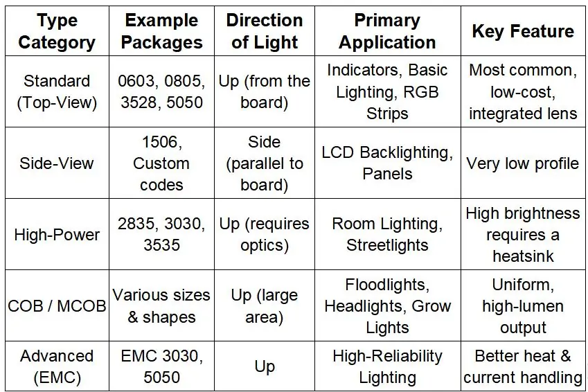
Summary Table for Quick Comparison
The accessible table clarifies the retained illustration below. Its categories overlap; package size alone does not specify power or quality.
| Category | Examples | Light direction | Typical use | Selection check |
|---|---|---|---|---|
| Standard top-view | 0603, 0805, 3528, 5050 families | Away from PCB | Indicators, strips, RGB lighting | Pinout, color, current, angle |
| Side-view | Manufacturer-specific side-emitting parts | Along PCB | Edge lighting, LCD light guides | Height and light-guide coupling |
| Higher-power SMD | Selected 3030, 3535 and other models | Usually top emission | General or exterior lighting | Rated current and thermal path; size is not a power rating |
| COB / MCOB | Common-substrate die arrays | Design-dependent | Lighting sources; separate display designs | Emitting area, optics, cooling |
| EMC package | Epoxy molding compound construction | Design-dependent | Selected lighting packages | Material description, not a separate power or reliability class |
6. How to Choose the Right SMD LED
Choose a surface-mounted device LED by its datasheet and operating conditions. For a complete display, also evaluate the module, driver, cabinet, and image performance:
- Light output: Compare intensity in candela or flux in lumens at the same current and temperature. Display luminance in cd/m² is a different system-level measurement.
- Viewing angle: Check intensity curves and screen color consistency at the required positions.
- Color: Specify RGB wavelengths or, for white lighting, CCT and color-rendering requirements.
- Footprint: Verify dimensions, polarity, pad layout, and pixel pitch for displays.
- Electrical and thermal limits: Check forward voltage, drive current, pulse duty, and cooling. Cree LED’s thermal-management guidance explains the heat path from junction to ambient.
7. SMD LEDs Installations By Eager LED Screens
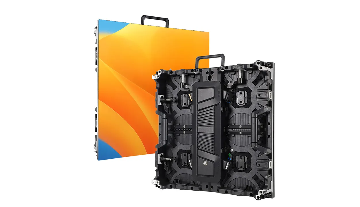
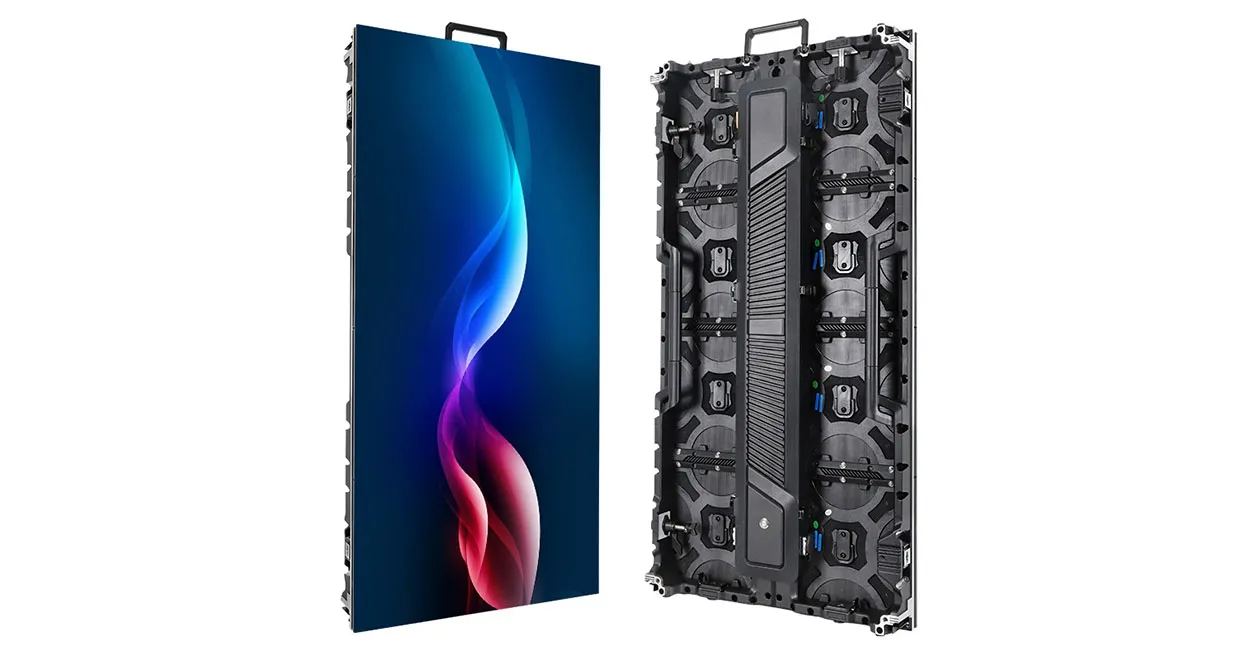
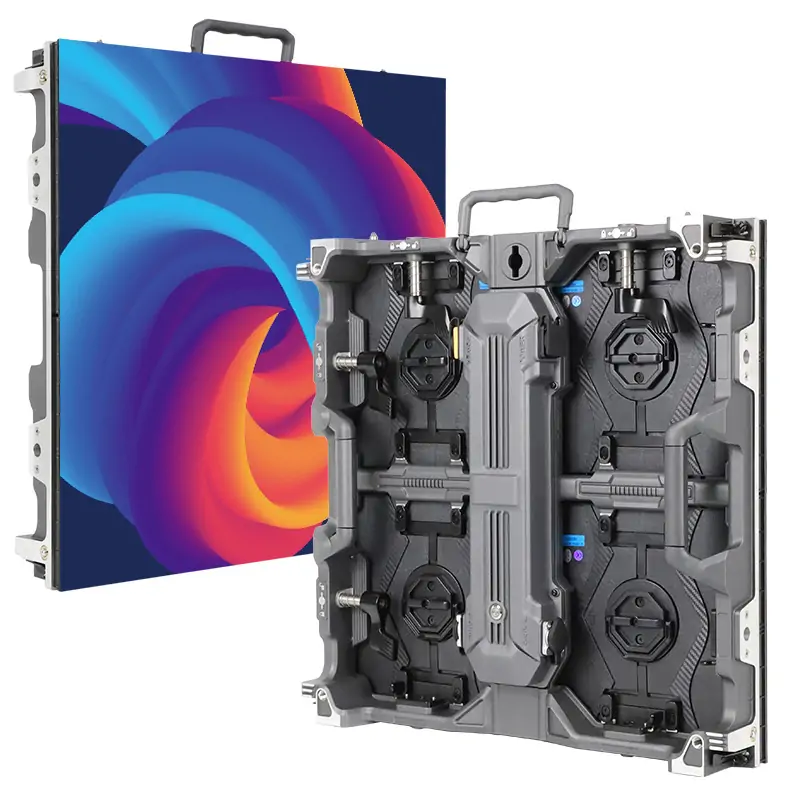
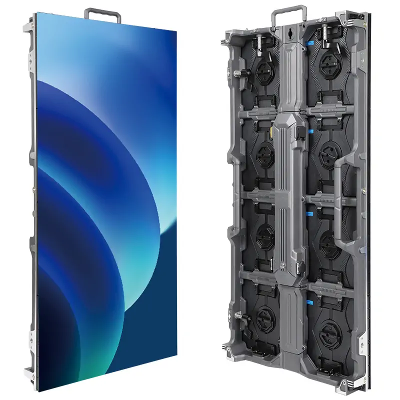
EagerLED supplies LED display products; choosing a finished screen differs from buying individual LED packages. For an installation proposal, provide screen dimensions, indoor or outdoor use, viewing distance, service access, and content requirements. Compare a module sample and its specifications before ordering. Our SMD vs COB display guide explains the packaging options for video walls.
8. Why SMD LEDs Are Widely Used in Displays
SMD packaging is widely used in displays because it supports compact RGB pixels and automated assembly. This does not establish a universal market-share lead. COB and other approaches also serve display applications; the appropriate choice depends on pixel pitch, environment, handling, and maintenance needs.
An RGB package brings three colors close together, but calibration, binning, drive settings, and optical design determine uniformity. Evaluate a screen from the intended viewing angles. A quoted maximum angle is not a promise of unchanged brightness and color across the entire range.
Automated placement supports repeatable production, but assembly quality still matters. “Lead-free” refers to material composition, not absence of electrical terminals or immunity to vibration. Kingbright’s SMD application notes address moisture, soldering, mechanical stress, and electrostatic-discharge precautions.
Package size contributes to the design, but cabinet depth, cooling, power supplies, and service access determine the final screen’s thickness and weight. An LED-backlit LCD television and a direct-view RGB LED sign should not be treated as the same display architecture.
9. FAQS
10. Conclusion
SMD identifies how an LED package mounts; the datasheet tells you what it can do.
Match dimensions, optical output, drive conditions, and thermal requirements to the application. For advertising LED screens, assess the complete module and cabinet as well as the LED package. Confirm specifications with the supplier and test a representative sample rather than selecting by package code alone.
 Novastar TB40 LED Controller: Smart Display Control Power
 Novastar VX1000 Pro: All-in-One LED Video Control Solution
Related Posts



Fill In Your Needs In Detail
Fill in the screen usage scene and size you need in “Content”.You will get a quote.