LED screens do not project images onto a surface. Each display produces the image, using thousands or millions of tiny red, green, and blue light sources. A control system converts every frame of a video signal into brightness instructions, distributes those instructions across the display, and refreshes the pixels fast enough for the viewer to see smooth motion.
That simple description hides a tightly coordinated system. Pixel pitch determines how closely the light sources are packed, LED modules form serviceable building blocks, cabinets provide structure and power, and receiving cards deliver the correct data to each section. This guide follows that complete signal path so you can understand how LED screens work and which specifications matter when planning one.
1. How Do LED Screens Work?
An LED screen works by turning a digital image into a grid of individually controlled light-emitting pixels. Each pixel normally contains red, green, and blue LEDs. By changing the intensity of those three channels, the display reproduces the colors and brightness required for one small point in the image.
The process happens in five stages:
- A media player, computer, camera system, or other source outputs a video signal.
- A video processor scales and formats that signal for the display’s exact pixel dimensions.
- A sending device divides each frame into data packets for the screen.
- Receiving cards inside the LED cabinets route pixel data to the correct modules and driver ICs.
- Driver ICs regulate the LEDs while repeated refresh cycles create a stable, continuous image.
Unlike an LCD, a direct-view LED display does not need a separate backlight or liquid-crystal layer. Its LEDs emit the visible light. That is why large-format LED video walls can deliver high brightness, strong contrast, seamless cabinet-to-cabinet construction, and flexible dimensions.
The display is modular rather than manufactured as one enormous panel. The controller treats the wall as one canvas, although the hardware may contain dozens of cabinets and hundreds of modules. Every part must agree on pixel position, timing, color, and brightness. A configuration error can appear as a displaced image, dark section, flicker, color variation, or scan lines on camera.
2. What Are the Main Components of an LED Screen?
Understanding the component hierarchy makes troubleshooting and specification much easier. A complete display is built from pixels, modules, cabinets, power and data hardware, and a control system.
2.1 RGB LEDs and Pixels
The pixel is the smallest addressable picture element. Most full-color screens combine red, green, and blue emitters in each pixel, using technologies such as SMD or chip-on-board packaging.
Pixel pitch is the center-to-center distance between adjacent pixels, measured in millimeters. A P1.5 screen has pixels spaced about 1.5 mm apart, while a P6 screen uses a 6 mm pitch. A smaller pitch fits more pixels into the same physical area and supports closer viewing, but it also increases component density, processing load, and cost. The practical choice should follow viewing distance, screen size, content type, and budget, as explained in EagerLED’s pixel pitch selection guide.
2.2 LED Modules
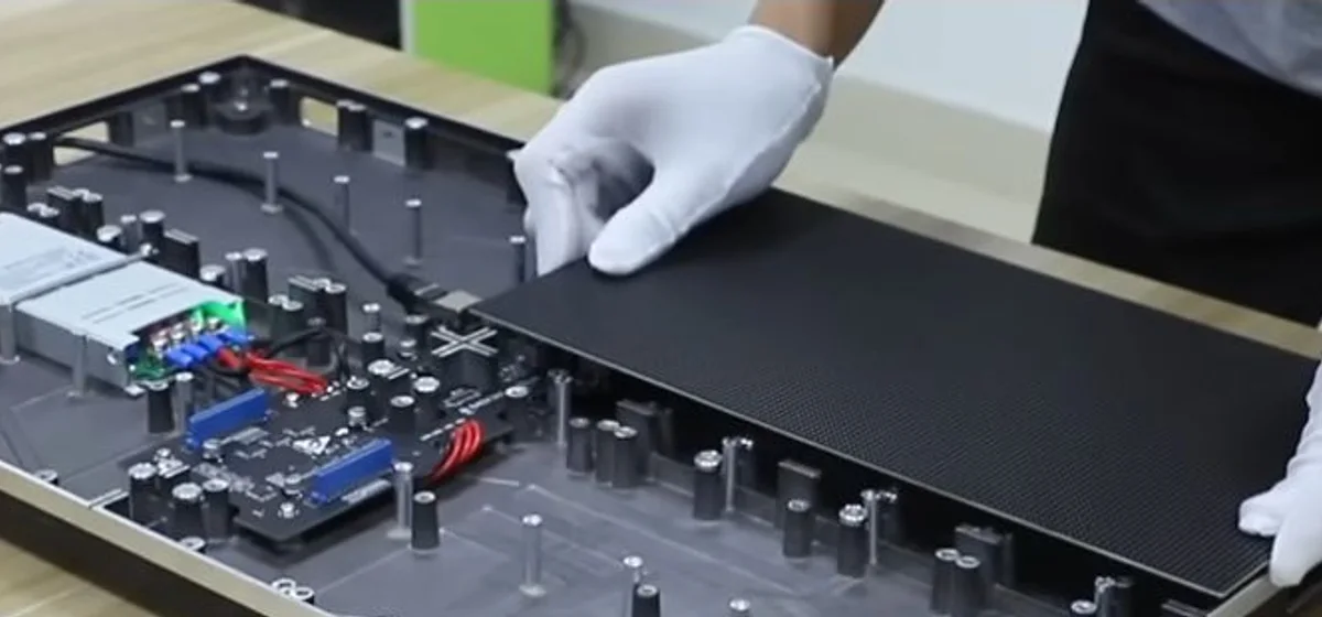
A magnetic LED module being aligned and installed into a front-service cabinet.
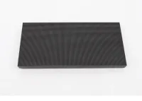
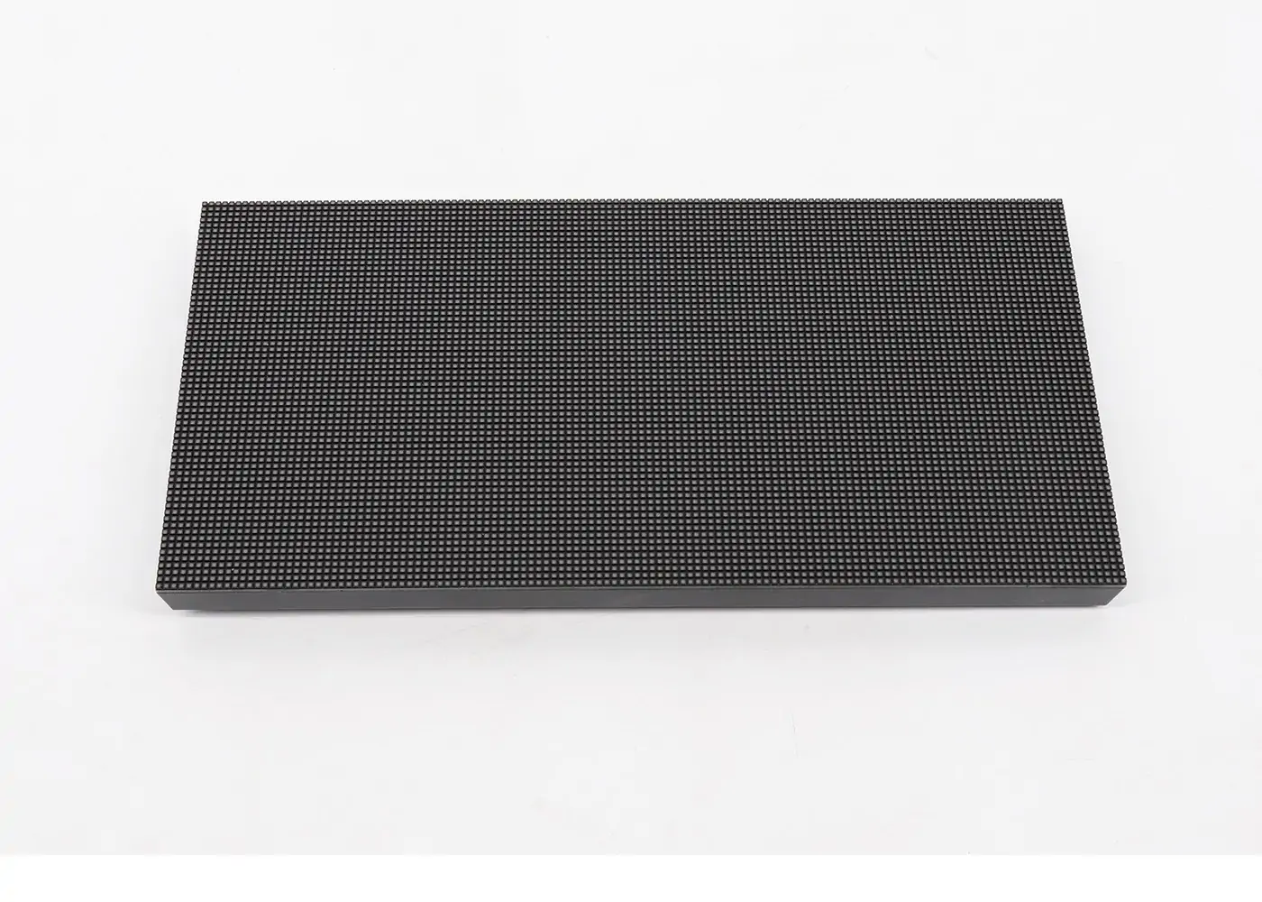
An LED module is a replaceable circuit-board assembly containing a fixed matrix of pixels. It typically includes LED packages on the front and driver ICs, connectors, and supporting circuitry on the rear. Multiple modules join to form the visible face of one cabinet.
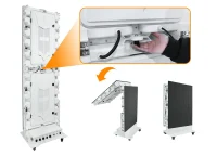
The module format makes large screens practical to manufacture and service. A technician can replace one affected module instead of removing the entire video wall. Magnetic front-service modules suit sites with no rear access; rear-service designs suit structures with maintenance space behind them. See EagerLED’s guide to LED screen modules for common formats.
Module seams must remain flat and consistent. Even when the electrical system is working, poor alignment can create visible dark or bright lines. Manufacturers therefore control PCB dimensions, masks, mounting points, and cabinet tolerances carefully.
2.3 Cabinets, Power Supplies, and Data Connections
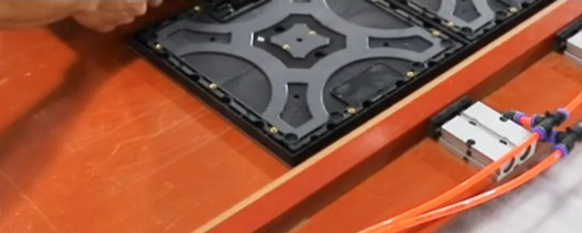
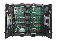
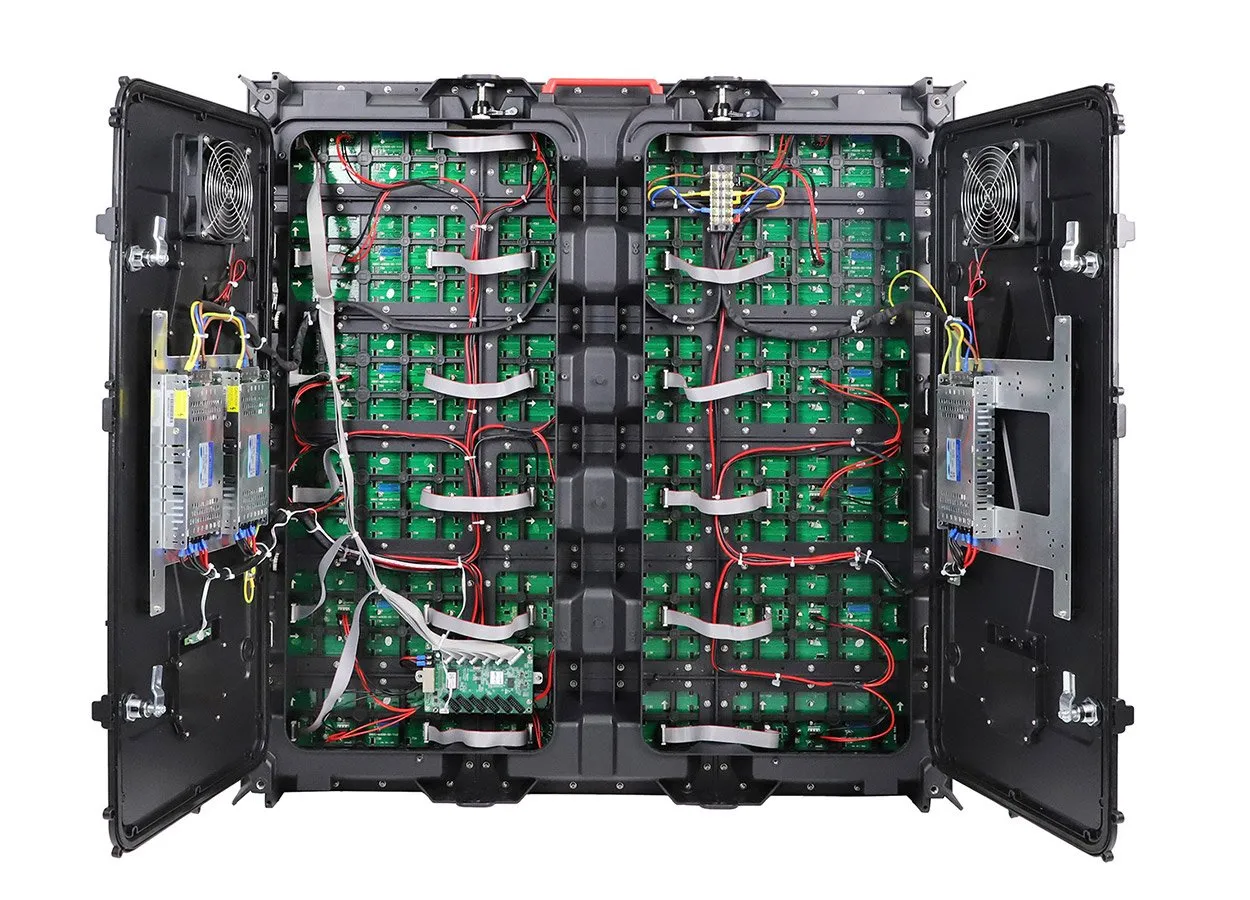
Rear-side components and connections prepared during LED cabinet assembly.
The cabinet holds modules, power supplies, receiving cards, hub boards, and cabling. Rental cabinets use quick locks for fast assembly, while fixed installations emphasize structural support, cable routing, environmental protection, and maintenance. Power supplies convert mains electricity to low-voltage DC and divide the load across the display. Proper grounding, protection, ventilation, and load calculations remain essential.
Data travels through network-style cables or fiber links. Redundant power and signal paths can protect critical installations, and a documented topology helps technicians isolate faults quickly.
2.4 Transparent LED Construction for Glass Facades
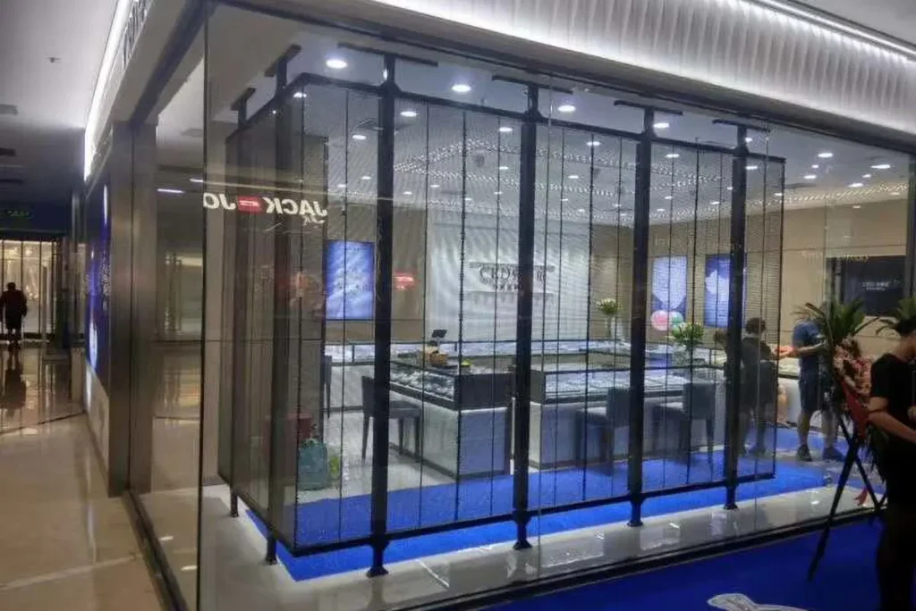
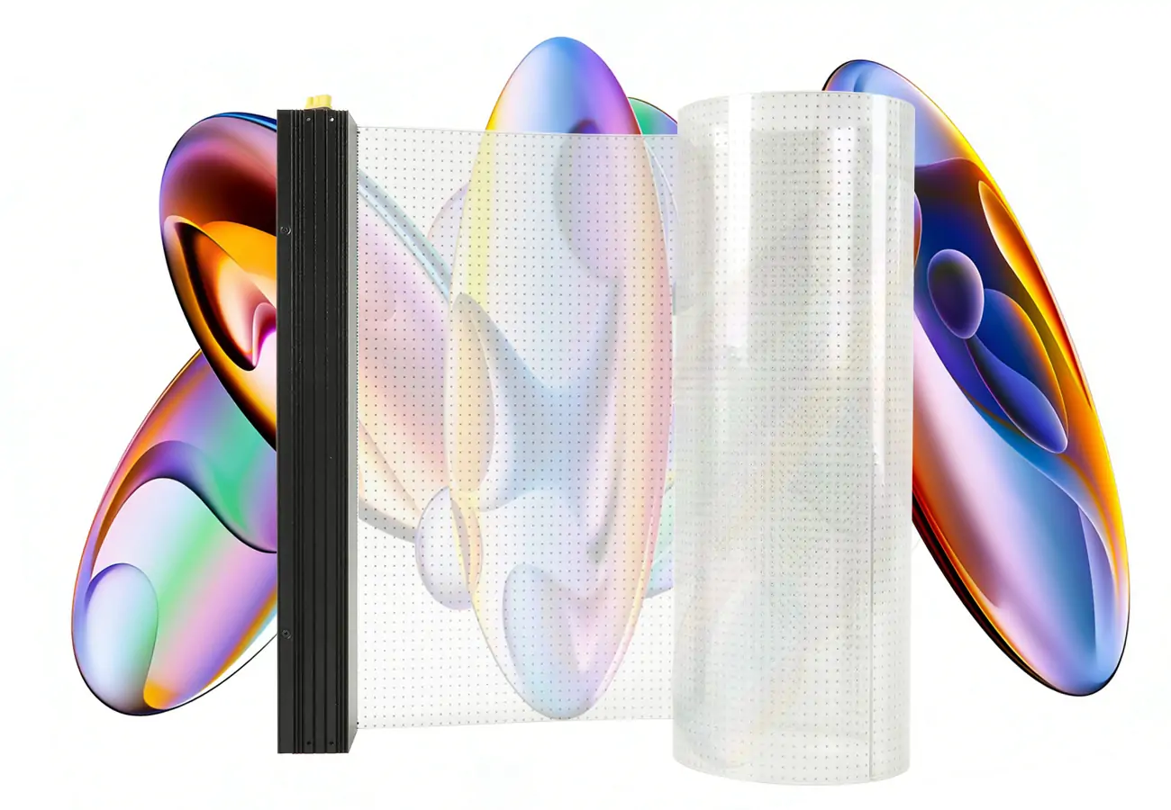
A transparent LED display follows the same RGB and control principles but arranges LEDs on narrow strips or open-grid modules. The empty space between the light-emitting structures allows daylight and sightlines to pass through, making the technology useful for retail windows, atriums, and glass curtain walls.
Transparency is a design trade-off, not an invisible-screen effect. More open area can reduce pixel density and close-view detail. Structural attachment, cable concealment, heat, wind load, access, glass geometry, and background contrast matter as much as the nominal percentage when selecting a transparent LED screen.
3. How Do RGB Pixels Create Images and Colors?
RGB pixels use additive color mixing. Red, green, and blue light combine directly in the viewer’s eye: red plus green produces yellow, green plus blue produces cyan, and all three at similar high intensity approach white. Turning all channels off produces black, although perceived black level also depends on ambient light and the reflectivity of the module surface.
The controller assigns a value to each color channel for every pixel. With 8-bit data, each channel has 256 possible levels, allowing about 16.7 million RGB combinations. Professional LED processing often uses greater internal bit depth so gradients remain smooth after brightness adjustment, color correction, or camera-oriented tuning.
LED brightness is commonly controlled through pulse-width modulation (PWM) and regulated drive current. During each refresh period, the driver switches a channel for controlled intervals; longer on-time produces greater perceived brightness. A camera can reveal flicker or scan bands if refresh timing and shutter settings are poorly matched.
Grayscale performance is especially important at low brightness. A screen may look excellent with saturated graphics yet show contouring in a dark gradient because it cannot separate nearby low-level values cleanly. High-quality driver ICs, suitable scan design, accurate processing, and calibration help preserve shadow detail.
Calibration corrects differences caused by component tolerances, aging, replacements, and temperature. Software applies per-pixel or per-module coefficients for a uniform white point, consistent color, and balanced luminance. Brightness should also match the environment: excessive indoor output is uncomfortable and weakens perceived black, while outdoor displays must overcome much stronger ambient light.
4. How Does the LED Control System Send Content to the Screen?
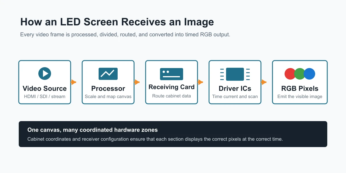
The LED control chain converts each video frame into precisely timed RGB output.
The control system is the bridge between ordinary video and the physical pixel map. Although brands use different hardware and terminology, the signal path usually follows this sequence:
Content source → video processor or sender → receiving cards → hub boards and driver ICs → RGB pixels
The source may output HDMI, DisplayPort, SDI, or a network stream. A processor scales and adjusts the image; the sender maps the canvas to output ports. Each receiving card stores its cabinet configuration and forwards the relevant rows and columns of data.
Driver ICs translate that data into precisely timed electrical output. In scanned modules, groups of LED rows operate in rapid sequence rather than all remaining active continuously. This reduces hardware requirements, but scan ratio, driver behavior, and timing affect brightness, grayscale, refresh performance, and camera results.
4.1 A Practical 8 × 4 Cabinet Example
Imagine a video wall made from eight cabinets across and four cabinets high. Each cabinet has a native resolution of 192 × 216 pixels. The complete display therefore measures 1,536 × 864 pixels:
- Width: 8 × 192 = 1,536 pixels
- Height: 4 × 216 = 864 pixels
- Total: 1,327,104 physical pixels
The processor scales the incoming program to that 1,536 × 864 canvas. The sending system assigns cabinet coordinates and routes the correct portion of every frame to each receiving card. The top-left cabinet receives one image region, the cabinet beside it receives the next, and the final cabinet in the bottom row receives the bottom-right region.
If two cabinet addresses are swapped, both cabinets light up but show the wrong regions. A broken data link may blank every downstream cabinet. An incorrect receiver configuration can cause repeated pixels, shifted rows, wrong color order, or abnormal scanning. Configuration files and cable maps should therefore be backed up after commissioning.
4.2 Synchronous and Asynchronous Control
A synchronous system displays a live input in real time and is common for events, broadcast environments, control rooms, and stage productions. An asynchronous controller stores scheduled content locally, making it suitable for storefront signs, information displays, and unattended advertising screens.
Some installations combine both approaches. The right architecture depends on latency, update frequency, redundancy, remote management, and the consequences of signal loss. When filming, frame rate, shutter angle, scan timing, and processor settings all influence visible artifacts; Brompton Technology’s ShutterSync is one example of camera-aware LED processing.
EagerLED official video: assembling an indoor rental LED screen from cabinets and modules.
5. Which Specifications Affect LED Screen Image Quality?
No single specification guarantees a good image. The best result comes from matching several parameters to viewing distance, content, ambient light, installation type, and camera use.
5.1 Pixel Pitch, Screen Size, and Resolution
Pixel pitch determines density, but total resolution also depends on physical dimensions. Calculate the canvas from actual cabinet and module dimensions rather than assuming a product name indicates resolution.
Detailed graphics and close viewing require higher density; a distant billboard may achieve the same perceived result with a wider pitch. EagerLED’s LED screen resolution guide and pixel pitch calculator guide help translate physical dimensions into pixel counts.
5.2 Refresh Rate, Frame Rate, and Scan Rate
These terms are related but not interchangeable. Frame rate describes how many complete video frames the source provides each second. Refresh rate describes how often the display updates its light output. Scan rate describes how module rows or groups are multiplexed by the driver circuit.
A screen can accept 60 fps content while refreshing its LEDs thousands of times per second. High refresh performance benefits cameras and fast motion, but grayscale, driver IC, scan mode, and processor compatibility also matter.
5.3 Brightness, Contrast, and Viewing Environment
Brightness is measured in nits. Indoor retail, conference, and studio displays need much less output than screens exposed to daylight. Excess indoor brightness causes discomfort and washed-out blacks; insufficient outdoor brightness reduces readability. Dark masks, low-reflectance surfaces, controlled ambient light, and correct settings improve contrast. Select an indoor LED screen around actual viewing conditions.
5.4 Grayscale, Color Depth, and Calibration
Color depth describes the number of digital levels available, while effective grayscale describes how well the installed screen reproduces those steps at its operating brightness. Processor bit depth, receiving-card configuration, driver IC performance, and calibration all contribute.
Ask suppliers to demonstrate dark gradients, neutral gray, skin tones, fine text, and motion at the intended brightness. A specification sheet cannot reveal low-brightness banding or camera behavior as clearly as a configured sample. EagerLED’s SMD vs. COB LED display guide also explains how packaging affects durability and fine-pitch applications.
Before approving a system, confirm these project-level items:
- Native screen resolution and content aspect ratio
- Minimum and typical viewing distance
- Indoor, outdoor, or window-facing ambient light
- Front or rear maintenance access
- Expected maximum brightness and normal operating brightness
- Refresh, grayscale, and camera requirements
- Primary and backup signal routes
- Power distribution, heat management, and structural support
These checks connect specifications to the real installation instead of treating the wall as isolated numbers.
6. FAQs About How LED Screens Work
7. Conclusion
LED screens work by coordinating millions of rapid electrical decisions. RGB pixels generate light, modules organize those pixels into serviceable units, cabinets provide structure and power, and the control system maps each part of a video frame to the correct physical location. The viewer sees one seamless picture because all of those layers operate in precise synchronization.
For buyers and system designers, the practical lesson is clear: choose an LED display as a complete system. Pixel pitch and brightness matter, but so do native resolution, driver performance, cabinet alignment, power and signal topology, calibration, viewing distance, maintenance access, and camera requirements.
EagerLED designs indoor, outdoor, rental, and transparent LED display solutions around these project conditions. To discuss screen size, installation environment, control architecture, or a suitable pixel pitch, contact the EagerLED team with your drawings, viewing distance, content format, and application requirements.
 Transparent LED Screen vs LED Film: Which Is Better for Glass Windows?
 How to Choose Front-Service vs Rear-Service LED Displays
Fill In Your Needs In Detail
Fill in the screen usage scene and size you need in “Content”.You will get a quote.