The NovaStar MRV532 receiving card connects a compatible LED controller to cabinet modules through 10 HUB320F connectors. It supports up to 512×512 pixels at 60 Hz with PWM driver ICs and 8-bit input; other configurations have lower limits. For an indoor fine-pitch LED screen, check module wiring, controller support and firmware before ordering. This guide covers specifications, price enquiries and setup.
1. What is NovaStar MRV532 Receiving Card?
NovaStar MRV532 is a receiving card from Xi’an NovaStar Tech Co., Ltd. It handles a section of an LED screen; multiple cards can be connected to serve larger displays. Confirm the exact sending-controller model and software workflow with your cabinet supplier rather than assuming compatibility across an entire controller series.
Use NovaStar’s MRV532 specification V1.2.0 (20 May 2025) as the reference here. Older sheets give different loading figures. Match the document, firmware and module configuration when replacing an existing card.
Key specifications:
- Outputs: 10 HUB320F connectors, up to 40 RGB real-pixel data groups.
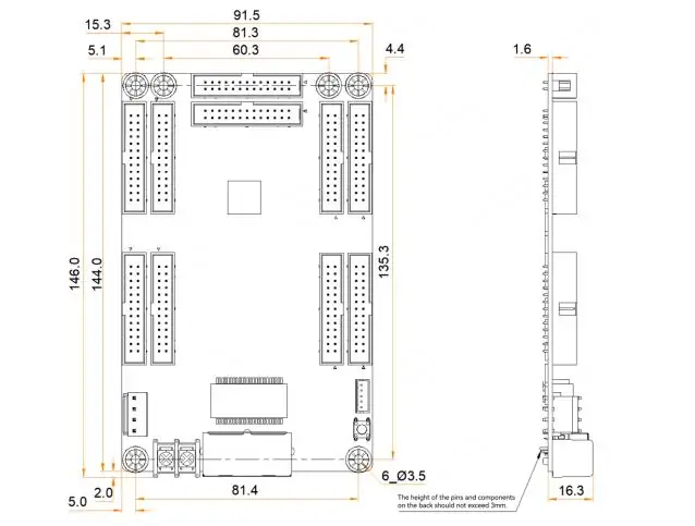
- Dimensions: 146.0 × 91.5 × 19.3 mm; weight 99.5 g. The drawing below shows six mounting holes; obtain a precision drawing before machining.
- Power: DC 3.8–5.5 V; rated 0.5 A and 2.5 W.
- Certifications listed: RoHS and EMC Class A.
2. Key Technical Highlights of NovaStar MRV532 LED Wall Receiving Card
2.1 NovaStar MRV532 Max Load Capacity
Capacity depends on driver IC type and source bit depth, not simply the screen’s resolution:
- PWM driver ICs: 512×512 at 60 Hz with 8-bit input; 512×256 with 10-bit or 12-bit input.
- Common driver ICs: 512×384 at 60 Hz with 8-bit input; 256×256 with 10-bit or 12-bit input.
These are published per-card limits. Check your LED module driver IC and wiring, cabinet dimensions in pixels, and controller port budget before assigning cabinets.
2.2 Advanced Display Enhancements
- Color management: Supports Rec.709, DCI-P3, Rec.2020 and custom gamut settings.
- 18bit+: Enhances low-brightness grayscale; this feature name does not mean 18-bit video input.
- HDR: Supports HDR10 and HLG. Check the complete source-to-screen configuration before promising HDR performance.
- Pixel-level calibration: Works with NovaStar’s calibration system to reduce brightness and color differences.
2.3 User Experience Improvements
- Dark or bright line adjustment: Corrects visible brightness differences at module or cabinet seams.
- Low latency: One frame at the receiving-card end requires driver ICs with built-in RAM; this is not total system latency.
- Rotation: Supports 0°, 90°, 180° and 270° orientations. Confirm the intended configuration before mounting cabinets.
2.4 Reliability and Maintainability
- Dual NCP backup: Provides a factory copy for restoration; it does not guarantee uninterrupted operation during a reset.
- Loop backup: Requires primary and backup connections to the controller. Test failover during commissioning.
- Module flash management: Stores and reads calibration coefficients and module IDs on supported modules.
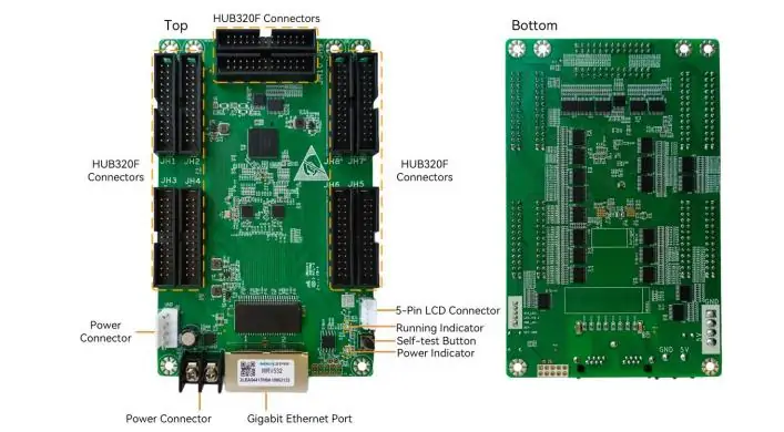
Backup behavior. The image below labels the HUB320F outputs, power connections, Ethernet ports, LCD connector, self-test button and status indicators.
3. Common LED Display Projects Using NovaStar MRV532 LED Receiver Card
Consider MRV532 for these projects after checking cabinet compatibility:
- Fine-pitch indoor screens: Evaluate low-brightness grayscale and uniformity at the intended viewing distance.
- Commercial video walls: Plan cabinet mapping, access and spare-card configuration.
- Control rooms: Test end-to-end latency and backup behavior against project requirements.
- Studio displays: Verify color settings and on-camera performance with the actual source and camera.
- Frequently serviced screens: Keep configuration and calibration backups for module replacement.
4. NovaStar MRV532 Receiving Card Price
There is no verified current unit price in this guide. Request a dated quote for the exact NovaStar MRV532 receiving card, specifying:
- Quantity, spare cards and required firmware.
- Cabinet/module configuration and included cables or accessories.
- Destination, shipping, taxes, warranty and lead time.
Compare the delivered total and support terms, rather than the card-only price.
5. NovaStar MRV532 Receiving Card Step-by-Step Setup Guide
Start with the cabinet supplier’s validated configuration and back up the working setup. The steps below are a commissioning checklist, not a substitute for the module-specific file.
Step 1: Hardware Connections
- With power off, check HUB320F pin assignments and cable orientation before connecting modules.
- Check supply voltage and polarity, then connect DC 3.8–5.5 V power.
- Connect the controller and cascade cards through the Gigabit Ethernet ports. Label the cable route.
Step 2: Software and Firmware Configuration
- Use the supplier-approved configuration software and load the correct module/cabinet settings. Verify mapping before saving to hardware.
- Back up settings before any NovaLCT receiving-card firmware update; confirm MRV532 firmware compatibility with the supplier.
Step 3: Testing and Calibration
- Disconnect Ethernet, press self-test twice to display a test pattern, then press again to change it.
- Reconnect the source and check mapping, grayscale and uniformity. Apply the correct calibration data where available.
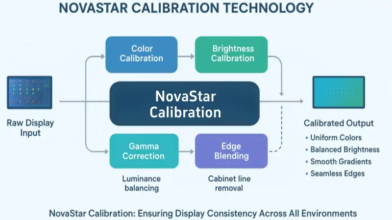
Self-test instructions. The illustration below summarizes color, brightness, gamma and seam correction; it is conceptual, not a software sequence or a guarantee of seamless results.
Step 4: Final Adjustments
- Verify startup and signal-loss images, then test normal playback and any configured backup route.
- Monitor temperature and voltage. Save the final configuration and calibration records for future servicing.
6. FAQs
7. Conclusion
Choose the NovaStar MRV532 receiving card by matching its loading limits, HUB320F connections and supported features to your cabinet. Keep a tested configuration and calibration backup, and validate performance with the actual controller and modules.
For purchase enquiries, provide the configuration checklist above. Consult NovaStar’s official technical resources and your cabinet supplier before changing firmware or replacing hardware.
 Top 10 LED Display Manufacturers in China (2026 List)
 Top 11 LED Screen Manufacturers in the World 2026
Related Posts
Fill In Your Needs In Detail
Fill in the screen usage scene and size you need in “Content”.You will get a quote.