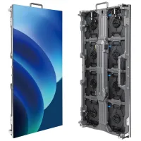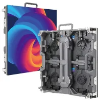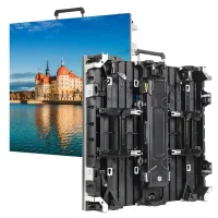
The NovaStar MCTRL300 is a synchronous LED sending controller with one single-link DVI input and two Gigabit Ethernet outputs, each rated for up to 650,000 pixels. The combined nominal load is 1.3 million pixels when both outputs serve independent cabinet chains. It suits a compatible, prepared video source and a smaller LED wall; provide upstream processing when you need source switching or image scaling. Check the actual cabinet map before choosing it.
This guide explains NovaStar MCTRL300 specifications, software, setup, price considerations, and common faults. It separates video input resolution from LED output capacity, shows worked cabinet calculations, and provides commissioning checks for rental and fixed installations. Use it to prepare a complete system specification before buying or replacing a controller, especially when adapting an existing LED wall with incomplete documentation.
1. What is the NovaStar MCTRL300 LED display controller?
The NovaStar MCTRL300 takes a live DVI picture and sends LED display data to receiving cards. Those cards distribute data to the modules inside the cabinets. Think of three separate jobs: the source creates the picture, the sending controller distributes the picture, and the receiving system drives the LEDs. A fault at any stage can produce a black or incorrectly mapped screen.
01. Understand the video and control paths
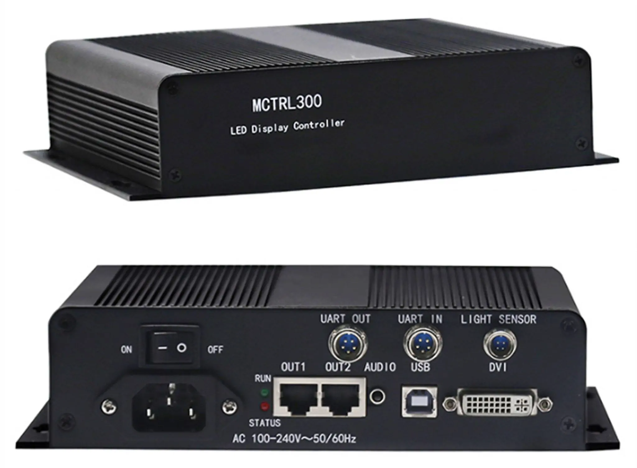
The normal video path is computer or video processor → DVI → MCTRL300 → LED data cables → receiving cards → LED modules. The configuration path is separate: a computer connects to the controller through USB. Connecting only USB does not deliver a live desktop image. This distinction is essential when NovaLCT detects the hardware but the wall still displays nothing.
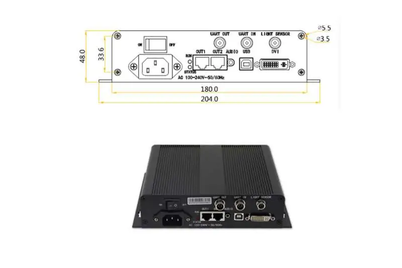
The RJ45 connectors serve the LED receiving system. Their familiar shape does not make them ordinary office-network connections. Follow the approved display topology and connect the screen directly as specified by the equipment supplier. Label both ends of every data cable so maintenance staff can identify the controller output and the first cabinet without tracing a long cable run.
02. Recognize the controller’s limits
The NovaStar MCTRL300 should be specified as a sending controller. Do not budget on built-in source switching, automatic full-screen scaling, a media playlist player, or a genlock connector. The manufacturer’s documented connectors and features do not establish those capabilities. If the project needs picture resizing or multiple sources, provide the appropriate upstream processing.
For example, a presentation designed for a widescreen computer monitor will not necessarily fit a narrow LED banner. Prepare a canvas that matches the intended display region, or use a processor to scale the image. The controller cannot create physical LED pixels that the cabinets do not contain. Likewise, a larger computer resolution does not increase the wall’s detail beyond its native pixel matrix.
2. NovaStar MCTRL300 specifications and key features
Check the hardware label and the relevant documentation before integrating an older controller. The compact reference below uses NovaStar’s MCTRL300 specifications V2.4.2, dated October 31, 2025. Input timing, output loading, and control connections describe different constraints; they should not be combined into a single “maximum resolution” claim.
| Item | Documented specification | Planning implication |
|---|---|---|
| Video input | One single-link DVI; 8-bit RGB 4:4:4 | Confirm the source output and any adapter. |
| Standard input timing | Up to 1920 × 1200 at 60 Hz; progressive | Input acceptance is separate from wall loading. |
| LED outputs | Two Gigabit Ethernet ports; up to 650,000 pixels per port | Count each port’s assigned cabinets. |
| PC configuration | USB Type-B | Use a separate video connection. |
| Other connections | Audio input, light sensor, UART IN/OUT | Confirm accessories and project requirements. |
| Cascading | Up to 20 devices through UART | Plan video distribution separately. |
| Enclosure | 204 × 160 × 48 mm; 1.04 kg | Allow space for plugs and service access. |
Reference: NovaStar, MCTRL300 LED Display Controller Specifications V2.4.2, connector and video-source tables. These values are hardware specifications, not a guarantee that every receiving-card configuration or custom timing will work.
01. Input resolution versus output capacity
The two output budgets give a nominal total of 1.3 million pixels. A full 1920 × 1080 wall contains 2,073,600 pixels, so accepting a Full HD source does not mean one NovaStar MCTRL300 can drive a Full HD LED wall. Always multiply the actual wall width by its height, then check how that load is divided between outputs.
Custom input dimensions introduce another common misunderstanding. A listed maximum width and a listed maximum height are separate timing examples, not permission to multiply both maxima into a huge square screen. Confirm the complete width, height, refresh rate, and output map together. Leave practical room for layout changes instead of treating a rounded marketing capacity as an exact design target.
02. Calibration, brightness, and redundancy
NovaStar documents pixel-level brightness and chroma calibration with NovaLCT and NovaCLB, a light-sensor connection, and Ethernet-port redundancy. These are useful system functions, but each requires the appropriate configuration and supporting hardware. Installing the sending box alone does not calibrate a mixed batch of modules or establish a tested backup path.
For the NovaStar MCTRL300, distinguish brightness adjustment from calibration. Brightness sets the overall light output; calibration addresses differences between individual LEDs or modules. If one replacement cabinet looks different, first check its module specification and configuration. Raising the brightness of the whole wall can make the mismatch more visible rather than resolve its cause.
A redundant cable route also consumes resources. Do not count a backup output as additional independent capacity at the same time. Define which failure the design is meant to survive, then test that exact failure during commissioning. Cable redundancy does not by itself cover loss of controller power, a failed video source, or every fault inside a cabinet.
3. Why the MCTRL300 works well: capacity planning and setup
The NovaStar MCTRL300 works best when the source, screen map, and receiving-card configuration are already understood. Its usefulness comes from a clear signal path and a repeatable setup process. The following calculations are illustrative design examples, not manufacturer-approved cabinet packages.
01. Calculate the screen and each output
Start with the exact cabinet resolution from the supplier. Multiply cabinet width by cabinet height to find pixels per cabinet. Then multiply by the number assigned to each output. If a wall contains different cabinet sizes, calculate each size separately and add the totals. Physical dimensions and a rounded pixel-pitch name are less reliable than the actual module matrix.
| Cabinet layout | Wall resolution | Total pixels | Proposed output loading | Budget assessment |
|---|---|---|---|---|
| 4 wide × 3 high | 768 × 576 | 442,368 | 12 cabinets on one port: 442,368 | Within one port’s pixel budget. |
| 6 wide × 4 high | 1152 × 768 | 884,736 | 12 cabinets per port: 442,368 each | Within two independent output budgets. |
| 8 wide × 4 high | 1536 × 768 | 1,179,648 | 16 cabinets per port: 589,824 each | Within budget; validate the full configuration. |
| 9 wide × 4 high | 1728 × 768 | 1,327,104 | 18 cabinets per port: 663,552 each | Exceeds both per-port budgets; redesign. |
In the third example, assigning twenty cabinets to output one would create 737,280 pixels on that port. The total wall still fits the nominal controller budget, but the unbalanced route does not. This is why a NovaStar MCTRL300 proposal should include a cable map rather than only a total pixel count. Receiving-card loading and input timing must also be checked.
02. Prepare MCTRL300 software and configuration files
Use the NovaStar software download library to locate NovaLCT and its documentation. Select a version appropriate for the controller, receiving cards, and operating system. A newer installer is not a substitute for checking compatibility. Keep the installer and the version number with the project records so a replacement service computer can reproduce the working environment.
For an existing NovaStar MCTRL300 installation, read and back up the working hardware configuration before changing it. Ask the cabinet supplier for the exact receiving-card file if it is missing. The RCFG and RCFGX configuration guide explains why a file must match the module and receiving system. Matching only the pixel pitch or cabinet dimensions is insufficient.
Keep configuration files distinct from firmware. Configuration describes how the screen is driven and arranged; firmware changes device software. Do not flash firmware simply because a screen is black. Record the fault, identify the hardware revision, and confirm that a specific update addresses it before planning an upgrade with a recovery route.
03. Connect and commission the NovaStar MCTRL300
Connect the source to DVI, the configuration computer to USB, and each planned LED data output to its first cabinet. Start with a known-good source and cable. If the source only offers HDMI, check a suitable HDMI-to-DVI connection with the actual output timing; an adapter does not provide scaling or make every source format compatible.
In NovaLCT, confirm communication with the sending device, check the receiving-card parameters, and build the screen connection map to match the physical cable order. Use the manufacturer’s NovaLCT synchronous-system manual for the installed version because labels and available controls vary. Send the verified configuration to the intended hardware and save it there, then keep a separate local backup.
Commission the NovaStar MCTRL300 with a numbered cabinet pattern before judging a video clip. A test image with corner labels, horizontal and vertical lines, and a visible border reveals reversed paths, missing sections, and unwanted cropping. Follow with red, green, blue, white, and grayscale patterns to inspect color order and consistency at a sensible brightness.
Finally, restart the system and confirm that the intended configuration persists. Test the actual presentation computer or media source, not just the installer’s laptop. Record source resolution, port assignments, receiving-card models, file versions, and cable labels. This handover information often saves more service time than an extra page of generic product features.
Consider a second planning example: a nominal four-meter by two-meter wall at 2.5 mm pitch suggests 1600 × 800 pixels, or 1,280,000 pixels. That is close to the nominal controller total, but it does not yet prove suitability. The actual cabinets may not divide into two equal, valid routes, and module dimensions may change the final resolution. Ask for the cabinet matrix and the proposed output map before accepting the design.
Compare that with the same physical area at 4 mm pitch: the approximate matrix is 1000 × 500, or 500,000 pixels. The physical screen area is unchanged, yet the pixel count is much lower. These arithmetic examples explain why a purchasing request that states only “eight square meters” cannot identify the correct controller. Always replace approximate pitch calculations with the supplier’s exact cabinet resolution before final approval.
4. NovaStar MCTRL300 price and purchasing checks
A useful NovaStar MCTRL300 price comparison starts with the delivered, configured system. A controller-only listing and a supported kit are different purchases, even when the photographs look identical. Request a current written quotation with currency, quantity, accessories, freight, taxes where applicable, warranty terms, and the scope of technical support. Historical marketplace prices are not a dependable project budget.
01. Compare complete quotations
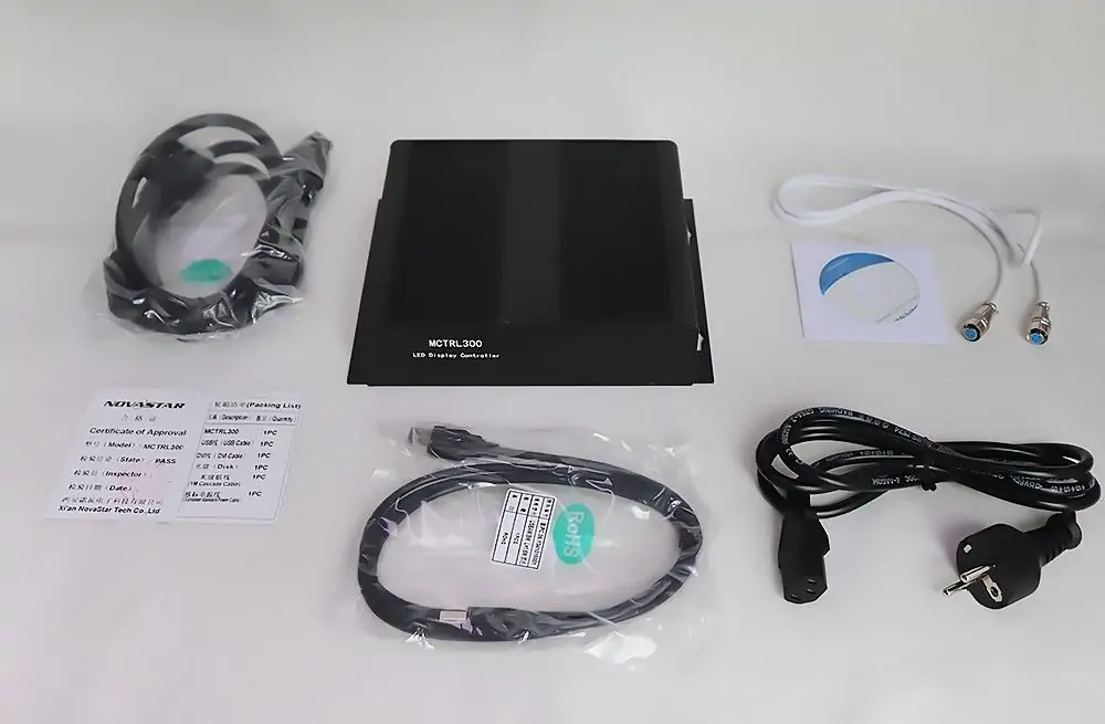
Ask whether the quotation includes the DVI cable, USB cable, power lead, and any required cascading accessories. Identify the source connector before ordering an adapter. Also establish who supplies the receiving-card configuration, who checks the cabinet map, and who handles commissioning. A low hardware price can become expensive if the installer must reconstruct an undocumented display during a short event setup window.
The NovaStar MCTRL300 may also require upstream processing for a particular job. Add that processor, its cables, and the time needed to configure it when comparing solutions. If a different controller combines the required functions, compare both complete designs using the VX400, VX600 and VX1000 selection guide. The right choice is the one that meets the application and service requirements within budget, rather than the box with the lowest advertised price.
For a replacement unit, ask the supplier to confirm the proposed hardware and firmware against the existing receiving system. Include photographs of the labels, the native wall resolution, and the current configuration files. “Same model name” is a useful starting point, but the commissioning check should prove that the replacement reproduces the intended picture and survives a restart.
02. Include support and downtime in the decision
For rental use, consider a tested spare, labeled cables, and an offline copy of the working setup. For a permanent installation, consider access to the controller, availability of a service computer, and the ability to identify a failed cable quickly. These costs belong in the purchasing discussion because they influence how long the screen may remain unavailable when something goes wrong.
To obtain a meaningful NovaStar MCTRL300 quotation, send EagerLED your screen and source details: cabinet resolution, cabinet quantity, receiving-card model, video connector, intended content, and whether backup is required. Include delivery location and schedule. A supplier can then check a specific system instead of pricing a controller whose suitability remains uncertain.
5. When to choose the NovaStar MCTRL300
Choose the NovaStar MCTRL300 when the wall fits its output budgets, the source can provide a compatible DVI signal, and the display uses a validated receiving system. Fixed signage, modest event backdrops, and workshop testing can be reasonable applications. The application name alone is not enough: two screens with the same physical dimensions can require very different pixel capacity.
01. Match the operating workflow
A permanently installed screen with one prepared content canvas can have simpler requirements than a conference display that accepts unfamiliar laptops throughout the day. For the conference, source switching, image scaling, and fast recovery may be more valuable than a small enclosure. Plan those capabilities explicitly rather than expecting the NovaStar MCTRL300 to solve them through a software setting.
For rental LED display projects, prepare a separate configuration for every approved cabinet arrangement. Name the files by layout and resolution, and include a matching cable diagram. If crews change the wall from six columns to eight, they must also confirm the source canvas and port distribution. Reusing an old file without checking the new arrangement can create repeated or missing image sections.
Outdoor cabinets do not make the control equipment weatherproof. Locate the controller and connections in a suitable protected environment with service access. If automatic brightness is needed, confirm the sensor arrangement and test its response at the installation. Sensor placement matters: direct illumination from the LED screen or a nearby lamp can give an unrepresentative ambient reading.
02. Know when another system is needed
Move beyond a single NovaStar MCTRL300 when the required pixel load cannot be distributed within its two outputs. Also reconsider the design when the brief requires native high-resolution input, several live sources, remote media scheduling, or camera synchronization. Those requirements call for verified processing, playback, management, or synchronization features in the selected system.
UART cascading provides a control arrangement for multiple devices; it should not be described as a complete video-wall expansion solution. Every controller still needs a planned video feed and a defined part of the canvas. For a larger wall, compare the complexity of multiple sending boxes with a controller designed for the required capacity. Document how the complete image remains correctly arranged.
03. Troubleshoot the NovaStar MCTRL300 systematically
When the image fails, separate power, PC communication, video input, receiving-card communication, and mapping. Change one variable at a time and record the result. If several settings are changed together, an accidental improvement may hide the original cause and make the fault return during the next event.
| Symptom | First checks | Next useful test |
|---|---|---|
| NovaLCT shows no hardware | Controller power, USB data cable, PC port, driver | Connect directly with a known-good cable and confirm PC device detection. |
| Hardware detected, wall black | DVI source, source output mode, video cable | Try a known-good progressive source before changing cabinet parameters. |
| Only some cabinets work | Per-port load, cable path, first failed cabinet | Inspect the transition from the last working cabinet to the next. |
| Picture repeats or appears scrambled | Cabinet dimensions, map, receiving-card file | Use numbered test blocks and compare them with the cable diagram. |
| Settings disappear after restart | Whether configuration was saved to hardware | Restore the verified backup, save, and repeat the restart test. |
| One cabinet has different colors | Module type, parameters, calibration data | Compare solid-color patterns before adjusting the whole wall. |
The NovaStar MCTRL300 status indicators offer an additional clue. In the V2.4.2 specification, a slowly flashing RUN LED indicates unavailable video, while normal flashing indicates available video. A breathing RUN LED indicates active Ethernet redundancy. Use the matching hardware documentation to interpret indicators; a valid input signal does not prove that the downstream cabinet map is correct.
If a receiving card is replaced, retain the original configuration and calibration records before loading anything onto the new card. When asking for support, provide the symptom, the last known working state, a connection diagram, and photographs of the relevant labels. A description such as “black after changing the source resolution” narrows the investigation much more effectively than “controller broken.”
Write an acceptance checklist before the installer arrives. Include the complete image border, readable text at the expected viewing distance, correct cabinet order, solid-color consistency, restart recovery, and operation from every approved source. If a backup path is part of the specification, describe the cable or device failure that will be simulated. Agree on the test conditions so that the customer and installer assess the same result.
For support handover, keep one clearly identified master configuration rather than several files named “final.” Record the date, wall dimensions in pixels, cable-map revision, and software version in a short project note. Store a second copy with the owner. When a cabinet is moved or replaced, update the record and repeat the relevant checks; otherwise the next technician may restore a configuration that belongs to an earlier layout.
6. NovaStar MCTRL300 FAQs
01. Which software does the NovaStar MCTRL300 use?
NovaLCT is the main configuration tool for this synchronous control workflow. Connect the PC through USB and use the version and documentation appropriate to the installation. NovaCLB supports calibration workflows. A media player or presentation application supplies the content separately; configuring the controller does not create a scheduled playback system.
02. Where can I find a NovaStar MCTRL300 manual?
Use the manufacturer’s MCTRL300 hardware specification for connectors, timings, and indicators, and the NovaLCT synchronous-system manual for configuration procedures. They serve different purposes. Match the document to the hardware and software in use, and retain the cabinet supplier’s configuration file alongside the manuals.
03. Does the NovaStar MCTRL300 have HDMI input?
Its documented video connector is single-link DVI. An HDMI source may be usable through a suitable adapter or converter, but the complete signal path needs testing. Confirm resolution and refresh rate, and do not assume that changing the connector also scales the picture or converts unsupported formats.
04. Can one MCTRL300 drive a 1920 × 1080 LED wall?
A full 1920 × 1080 wall contains 2,073,600 physical pixels, beyond the nominal 1.3 million-pixel output budget. Input resolution and physical LED loading are different. A smaller wall may display a selected or externally scaled image from that source, provided its map and per-port loads are valid.
05. Can the NovaStar MCTRL300 play videos without a computer?
A separate compatible video source can supply the live picture; it does not have to be the configuration computer. However, the controller should not be treated as a standalone playlist player. The selected media source must remain active, and the complete system should be tested after power is restored.
06. Why does MCTRL300 software detect no hardware?
Check controller power and the USB communication path first. Try a known-good data cable, a direct PC connection, and the appropriate driver. Video and USB are separate paths: a working DVI picture does not prove USB communication, and successful USB detection does not prove that a usable video signal is present.
07. How should I compare NovaStar MCTRL300 prices?
Compare a current delivered quotation for the same accessory set, support scope, and warranty. Include any adapter, processor, configuration work, or spare needed by the project. Ask for compatibility confirmation against the wall resolution and receiving-card model before treating a low advertised price as a complete solution.
08. Does using both Ethernet ports automatically provide backup?
No. Two independent cabinet chains use the ports for additional loading. Redundancy requires a compatible topology and correct configuration, followed by a failure test. Identify the failure you need to cover and allow for backup capacity. A second cable alone does not protect against every source, controller, or power fault.
7. Conclusion: specify the complete LED system
The NovaStar MCTRL300 is a practical sending controller when its input, output, and configuration requirements match the display. Start with the native cabinet pixels, allocate every receiving-card chain, and confirm the source format. Add processing when the content needs scaling or switching, and treat redundancy as a tested design rather than an assumption.
A successful NovaStar MCTRL300 installation also needs a reliable handover: a saved hardware configuration, local backup files, cable labels, and a record of the source settings. Those details make maintenance repeatable. Before ordering, send the complete project information for a compatibility check so that the controller, receiving cards, modules, and intended content form one workable system.
Technical references: NovaStar’s MCTRL300 LED Display Controller Specifications V2.4.2 (October 31, 2025) and NovaLCT LED Configuration Tool for Synchronous Control System User Manual V5.4.8. Consult the matching documents for your installed versions. Pixel calculations and commissioning examples in this article are explanatory project-planning examples, not published test results.
 NovaStar H5 Video Wall Splicer: Specs, Cards & Setup
 OLED vs LED Display: Differences and Which to Choose
Related Posts
Fill In Your Needs In Detail
Fill in the screen usage scene and size you need in “Content”.You will get a quote.