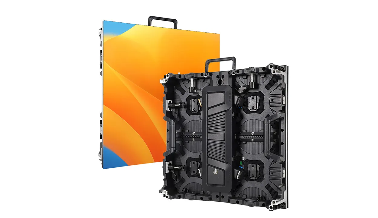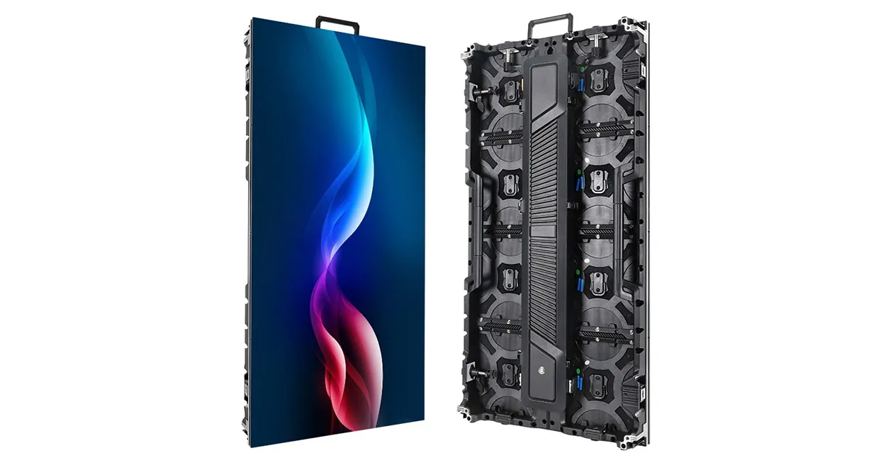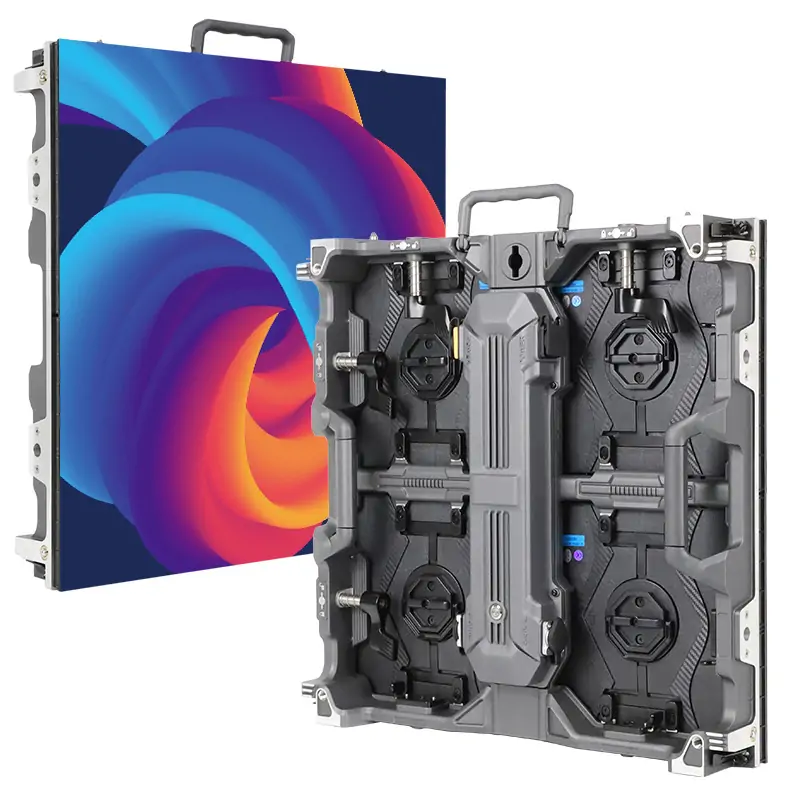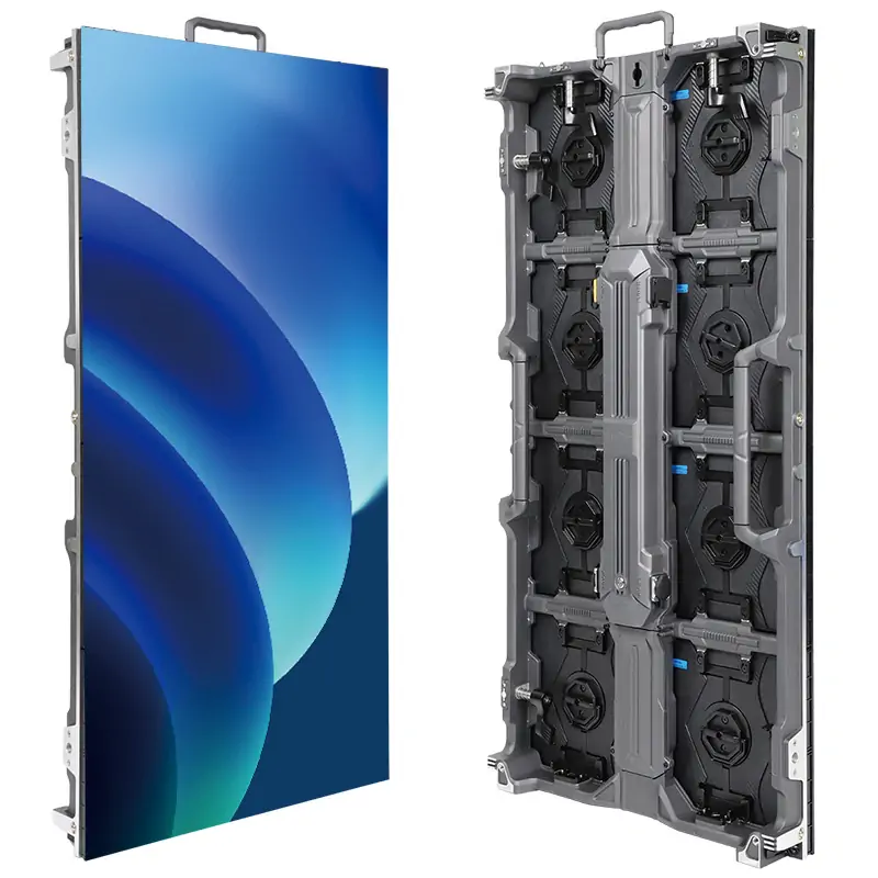
The NovaStar H15 is a 15U modular video wall splicer that combines multi-source video processing with LED sending when suitable output cards are installed. The standard chassis supports up to 10 output cards; H15 Enhanced supports 16. Actual pixel capacity depends on the sending card, bit depth, frame rate, and backup configuration.
For a fine-pitch LED wall, choose the configuration from the wall’s pixel dimensions and required sources, not the chassis name alone.
This guide explains the published specifications, practical setup checks, cost factors, and comparisons. It is a documentation-based review, not a measured hardware benchmark. The technical reference is NovaStar’s H15 Specifications V1.15.0, released May 30, 2026, with its H Series User Manual V1.15.0.
1. What is the Novastar H15?
The H15 can operate as a video splicer alone or as a combined splicer and LED controller. Video output cards feed downstream equipment; LED sending cards drive compatible receiving systems. This distinction matters when ordering: an HDMI output configuration and a direct LED sending configuration require different hardware and cabling.
NovaStar positions the H15 for fine-pitch displays in control rooms, presentations, broadcasting, and rental installations. It supports 10-bit processing and HDR10/HLG, but the supported resolution, color format, and frame rate depend on the selected connectors. A 4K input specification does not guarantee every 4K/10-bit combination throughout the system.
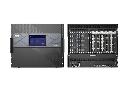
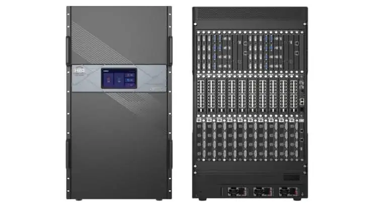
The chassis offers up to 30 input cards, with output-card maxima of 10 or 16 according to the variant. Plan the actual slot arrangement before purchase: some sending cards occupy two slots, and shared I/O positions affect the available combination. See the rear-panel diagrams and card list in the official H15 datasheet.
2. Technical Specs of Novastar H15
Check three separate limits when specifying a NovaStar H15: chassis slots, the capacity of each installed card, and the receiving system’s capacity at the intended signal format. The published maxima below are configuration limits, not measured performance for every installation.
2.1 Chassis, dimensions, and power
NovaStar lists dimensions of 482.6 × 683.0 × 533.0 mm, a chassis net weight of 41.1 kg, and maximum power consumption of 900 W. Card loading changes the installed weight. Two power supplies are standard and two redundant supplies are optional; both standard power connectors must be connected in use. These are manufacturer specifications, not typical measured power draw.
Allow for rack support, rear connectors, cable bend radius, airflow, and service access. Confirm the completed rack’s load and electrical requirements with the integrator before delivery.
2.2 Input card ecosystem
Input options include HDMI, DisplayPort, DVI, SDI, VGA, CVBS, HDBaseT, fiber, IP decoding, NDI, and ST 2110, depending on the card. Record the exact card model alongside each source’s resolution, frame rate, bit depth, and audio needs. An IP camera decoder is not interchangeable with an NDI or ST 2110 interface.
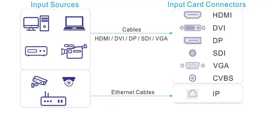
The former HDMI 2.0 card installation restrictions were removed in specification V1.12.0. Do not apply an old I-1 to I-8 rule to a current configuration. Use the current card specifications and slot diagram, and confirm compatibility with the installed firmware. The connection image below illustrates the physical input arrangement; match each source to its labeled card connector.
2.3 Output cards and pixel loading
The standard H15 supports up to 10 output cards and 40 output channels; H15 Enhanced supports 16 cards and 64 channels. LED pixel loading depends on the sending-card model. “Enhanced” in a card name and “Enhanced” in the chassis name are separate choices.
| Sending card | Per card | H15 | H15 Enhanced |
|---|---|---|---|
| H_20xRJ45 | 13 million | 130 million | 208 million |
| H_4xfiber | 20.8 million | 208 million | 332.8 million |
| H_4xfiber (enhanced) | 26 million | 260 million | 416 million |
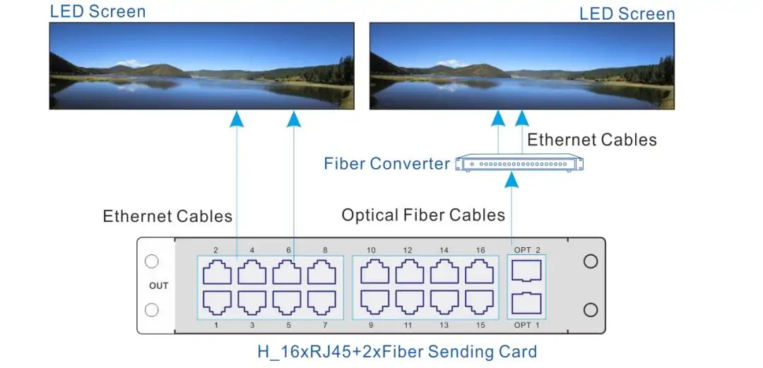
Source: H15 datasheet, specifications and sending-card sections. Figures are pixels, with the maximum number of matching cards; higher bit depth and backup allocation can reduce usable capacity. Check per-port and width/height limits too. Fiber and RJ45 sending cards cannot load the same screen together; standard and enhanced fiber sending cards also cannot share one screen. Follow the illustrated sending path through the appropriate fiber conversion equipment or Ethernet outputs to receiving cards.
3. Novastar H15 Features that Actually Matter
3.1 Hot swap capability
The input and output cards support hot swapping, which can simplify maintenance. However, removing a card interrupts the signals carried by that card unless a compatible, configured backup path takes over. Hot swapping alone does not guarantee uninterrupted display. Confirm the supplier’s bill of materials: the required input, sending, preview, and optional redundancy hardware must be specified explicitly.
3.2 4K/8K with real HDR
HDR10/HLG and 10-bit processing are supported, with important connector limits. For example, the datasheet lists HDMI 2.0 RGB/YCbCr 4:4:4 at 4096 × 2160/60 Hz for 8-bit, but at 30 Hz for 10-bit; 10-bit 4:2:2 supports 4K/60 Hz. The HDMI 2.1 input supports up to 8192 × 4320/30 Hz. Consult the Video Source Features table for the exact mode.
Verify the source, input card, output card, receivers, and display settings as one chain. Test HDR material and fine text before committing to a color format.
3.3 Layer management
Both chassis variants list a maximum of 160 layers. The per-card budget is resolution dependent: standard H15 supports up to 16 2K layers, while Enhanced supports 10; each supports up to four 4K or two 8K layers per card. These are alternative budgets, not quantities to add together. Connector capacity affects layer accounting, even when the source connected to it is lower resolution. Plan each screen’s simultaneous layers and transitions before selecting cards.
3.4 Web based control — mostly good, sometimes annoying
The H-Series web interface provides cross-platform control from Windows, Mac, iOS, Android, and Linux without installing a dedicated control application. Connect through the management network and use the device’s configured IP address. This covers web operation; receiving-card configuration can still require NovaLCT or another supported NovaStar tool.
Use a desktop-sized display for detailed screen mapping and layer placement. Give screens, inputs, and presets clear names so another operator can understand the project. Before handover, test the actual browser and workstation that staff will use, and export the working configuration for recovery.
4. What it’s Actually Like to Use Novastar H15
4.1 Image quality
Evaluate image quality with the intended cabinets and content. Check grayscale ramps, near-black detail, fine text, motion, and camera footage where relevant. Record input format and output settings so results can be reproduced. No end-to-end latency measurement is provided here; camera, source, scaling, processing, and receiver settings all influence the final delay. Measure the complete chain for IMAG, esports, or camera-critical work.
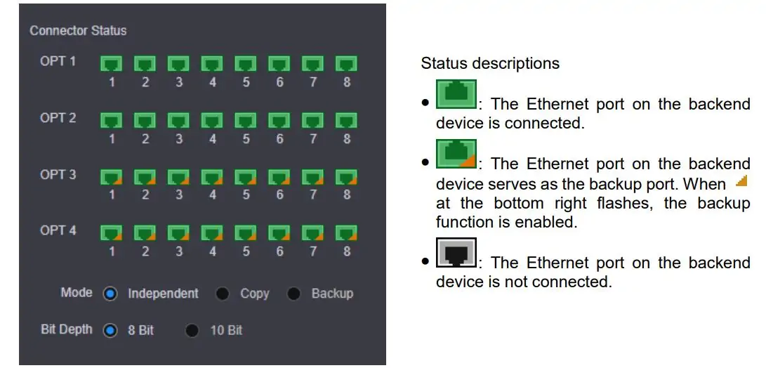
The bit-depth screenshot shows a setting, not proof of improved source detail. Converting an 8-bit source to a 10-bit output does not restore missing gradations, and it does not inherently cause banding. Check color range, HDR mode, processing settings, and port capacity when changing bit depth. Use known test patterns to separate source limitations from mapping or display faults.
4.2 Reliability under load
The H15 supports redundancy options, but availability depends on the hardware and configuration. Standard dual supplies are distinct from the two optional redundant supplies. Device backup, source backup, and sending-port backup require separate planning. NovaStar excludes NDI and IPC sources from source backup relationships in the current limitations on use.
During commissioning, test each intended failure mode and recovery path. Document which screen area remains affected if a card, cable, source, or power feed fails.
4.3 The learning curve — depends where you’re coming from
Operators familiar with NovaLCT will recognize screen mapping concepts, but H-Series web layouts, connector modes, and presets require separate practice. Allow time to build and restore a test project rather than assuming a fixed learning period.
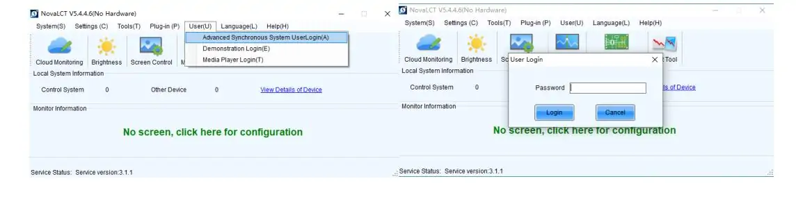
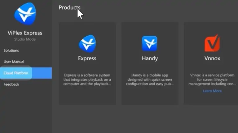
The NovaLCT image below identifies the companion configuration software. Follow the H Series User Manual V1.15.0 alongside the manual matching your installed NovaLCT version. Check firmware compatibility before following a tutorial recorded on a different release.
5. What Novastar H15 Actually Costs
There is no single reliable NovaStar H15 price for every project. NovaStar’s technical documentation does not provide a universal retail price, and a chassis-only offer cannot be compared directly with a configured system. Request a dated, itemized quotation for the standard or Enhanced chassis in your delivery region.
The quote should list exact input and output cards, optical modules and converters, optional power supplies, spare cards, rack accessories, freight, tax, commissioning, and warranty support. State the number of live sources and screens, not just total pixels. Ask the supplier to identify any components excluded from the quoted price.
Compare complete systems against the same signal list and acceptance tests. A fixed-I/O processor may suit a small wall with few sources; a modular splicer may suit several screens and many simultaneous feeds. Calculate the total installed cost, including receiving-card compatibility, required external equipment, and operator training.
Consider H5 or H9 when their verified slot and layer budgets cover the project. Choose the H15 when additional I/O and expansion capacity are needed. Leave a documented allowance for expected new sources or screens, but avoid buying unused capacity without a plan. Confirm any future card upgrade against the chassis and firmware before including it in a budget.
6. How Novastar H15 Stacks Up Against the Competition
6.1 Novastar H15 vs Brompton Tessera
The H15 and Brompton Tessera serve overlapping LED-display applications but emphasize different system designs. H15 provides a modular platform for many inputs, screen layouts, and layers. A Tessera system must be evaluated with its compatible panels, receiver hardware, distribution equipment, and source-routing requirements.
For camera work, Brompton documents system-wide Genlock and phase adjustment and ShutterSync on SX40 and S8 processors. H15 also supports Genlock; its presence alone does not establish equivalent on-camera performance.
Compare the proposed systems with the intended camera frame rate, shutter settings, content, and cabinets. Check calibration workflow, latency, spare equipment, and the operator’s requirements. There is no measured head-to-head benchmark here supporting a universal quality or reliability ranking.
6.2 Novastar H15 vs Colorlight and Linsn
Colorlight and Linsn should be evaluated by exact processor and receiving-card model. A lower-cost unit with sufficient pixels may still differ in input count, simultaneous layers, backup options, or mapping limits. Conversely, a simpler installation may not require the H15’s modular capacity.
For each proposal, obtain the manufacturer’s current datasheet, compatible receiver list, firmware requirements, and local service terms. Compare the same wall resolution, signal formats, redundancy plan, and commissioning scope. Brand-wide claims about inferior reliability or support are not a substitute for that evidence; verify the supplier’s support arrangements before purchase.
7. How to Set up Novastar H15?
7.1 Screen configuration via the web interface
Connect the control computer to the H15 management network and open its configured IP address in a supported browser. Confirm communication before connecting the live sources. Set output resolution and frame rate first; fiber sending cards also require the correct connector working mode on the Device page.
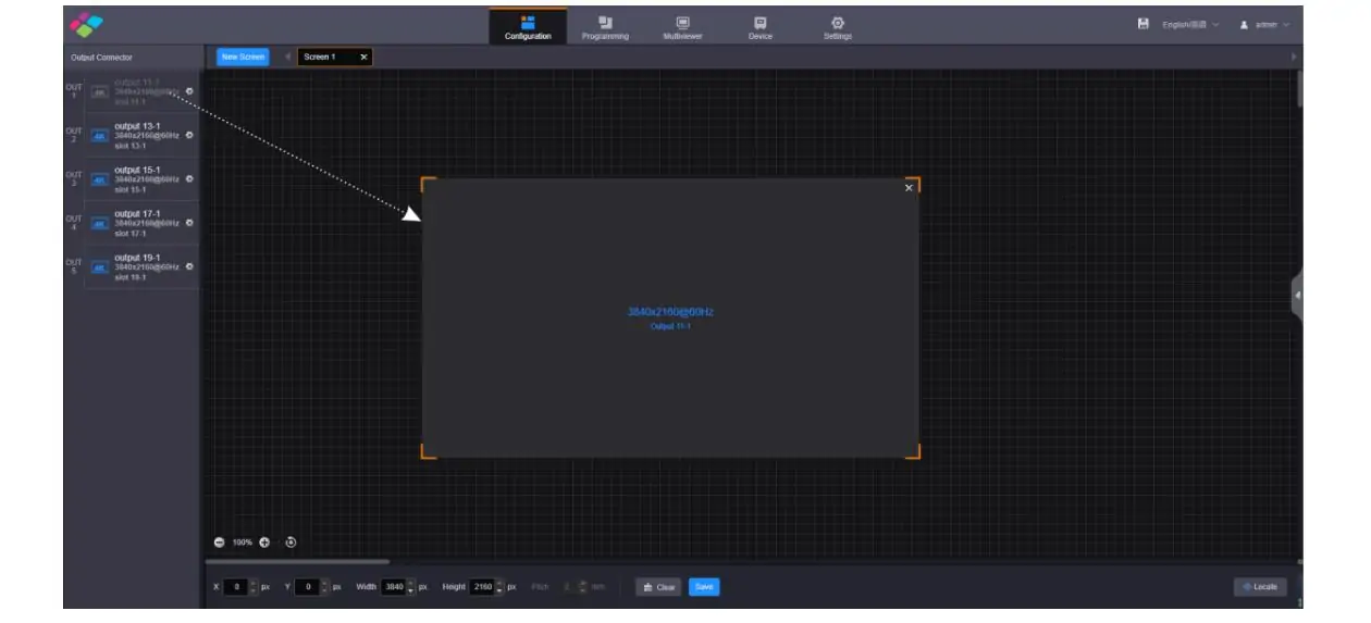
In Configuration → New Screen, select Screen, enter a meaningful name, set rows and columns for the screen structure, drag the required output cards/connectors onto the layout, and save. This follows the manual’s LED-screen setup procedure. The screenshot illustrates the web layout; receiver-level cabinet wiring is configured separately. Label outputs against the physical cable plan.
7.2 RCFGX files and cabinet mapping
Obtain the correct .rcfgx receiving-card configuration from the cabinet supplier, such as EagerLED for its supplied cabinets. Verify the receiving-card model, driver IC, scan arrangement, and cabinet resolution. Back up working receiver parameters before making changes; do not substitute an unrelated cabinet file.
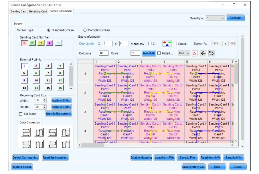
The NovaStar setup manual uses NovaLCT for screen connections with the listed LED sending cards. Select the communication port, set receiver rows, columns, and loading dimensions, then draw connections in the actual Ethernet wiring order and send the configuration to hardware. The screen-mapping image below illustrates those controls. Verify the physical result with test patterns and save the confirmed configuration for restart and recovery.
7.3 First power-up checklist
- Verify the cabinet configuration file and receiving-card resolution against the supplier’s records.
- Calculate loading for every output port. H_20xRJ45 is listed at up to 650,000 pixels per port at 8-bit and 325,000 at 10-bit; verify the selected frame rate and receiver limits.
- Confirm source resolution, color format, range, HDR mode, and bit depth across the signal chain.
- Match screen mapping to the wall’s real pixel dimensions and cable order; test edges and cabinet boundaries.
- Test the intended video frame rate, including fractional rates where used. Video frame rate and the panel’s LED refresh rate are different specifications.
- Test presets and configured failover paths, then save and export the working configuration. Confirm it survives a controlled restart.
8. FAQs
9. Conclusion
The NovaStar H15 is worth evaluating when a project needs modular inputs, several screen layouts, and substantial LED sending capacity. Its useful capacity is determined by the selected cards and operating format, not the largest number on a specification sheet.
Before ordering, confirm the slot plan, per-port loading, receiver compatibility, required layers, and backup behavior. Request an itemized quote and agree on practical image, latency, and recovery tests.
For a proposed wall, share the cabinet model, pixel dimensions, input list, and redundancy requirements with your integrator. Use those details to select the chassis and cards, then retain the final mapping and configuration files with the installation documentation.
 13 LED Screen Suppliers for Singapore: 2026 Guide
 How to Use an LED Pixel Pitch Calculator: 5 Steps
Related Posts
Fill In Your Needs In Detail
Fill in the screen usage scene and size you need in “Content”.You will get a quote.