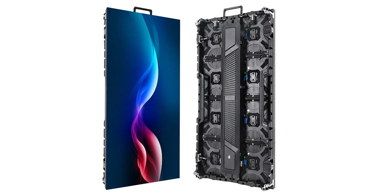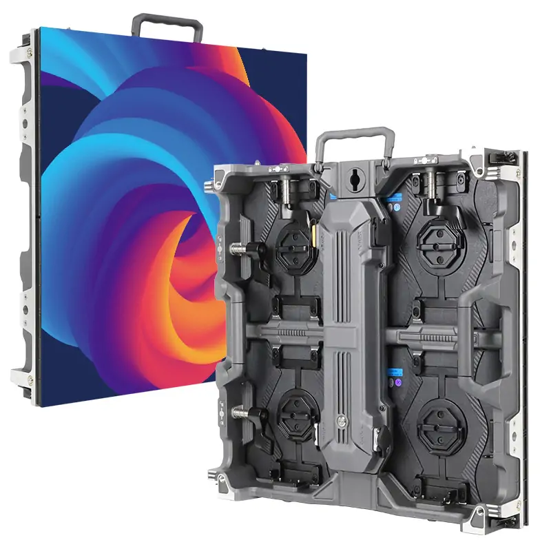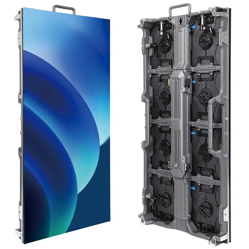
Front service LED wall planning starts with proving that every replaceable component can leave the finished wall from the room side. Confirm the module, power supply, receiving card and cable access paths before approving the cabinet grid, mounting section and decorative surround. A thin cabinet alone does not establish a serviceable installation.
This guide is for AV integrators preparing an indoor fixed-installation purchase specification. It focuses on the decisions that should be closed before fabrication: physical fit, native resolution, installed depth, access, utilities and a witnessed maintenance demonstration. The objective is a design that can be quoted, built and maintained without relying on an undocumented assumption.
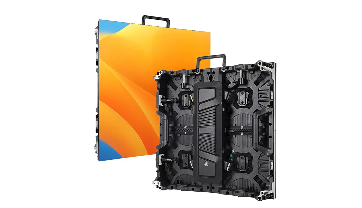
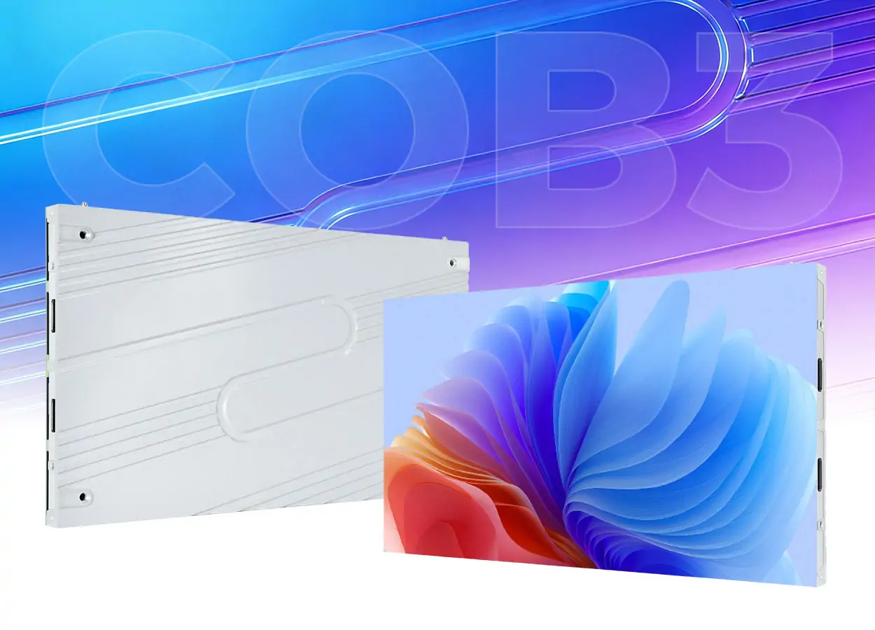
EagerLED’s EA640F2 provides a concrete product reference for cabinet geometry and front access. The calculations below are explicitly identified planning examples, not approved construction drawings or promises for every configuration. If you are still comparing mounting approaches, start with our indoor LED screen installation methods guide.
1. Front Service LED Wall Planning Starts With the Service Boundary
Front access should describe a complete repair route, not just a removable LED module. Ask the supplier to identify which parts can be replaced from the front, which require adjacent modules to be removed, and which need separate access outside the display. Put these answers on the same drawing that shows the finished wall.
The EA640F2 product page describes front replacement of modules, power supplies and LED control cards. That is a useful starting point, but the installation still needs space for the selected extraction tool, the technician’s hands and the component removal path. Confirm the arrangement for the exact model revision and supplied parts.
In front service LED wall planning, a demonstration on a loose cabinet is weaker evidence than a demonstration inside a representative surround. A lip, reception counter, glass barrier or speaker can obstruct the tool even when the module itself is removable. Record the closest obstruction and show how the technician will reach the top row.

| Item | Evidence to request | Reason to revise the design |
|---|---|---|
| LED module | Removal with the approved tool inside the proposed border | The border traps the module edge or prevents the tool from seating |
| Power supply | Safe isolation, access to terminals and a demonstrated extraction path | The unit can be seen but cannot be withdrawn without removing the wall |
| Receiving card and hub connections | Connector identification, access and configuration recovery procedure | Unlabeled connections or a missing backup make replacement uncertain |
| Incoming power and signal | Accessible termination locations and a labeled cable route | A joint or disconnect becomes concealed behind permanent finishes |
| Top and corner positions | Practical technician access with the planned equipment | A floor-level demonstration does not represent the installed position |
Agree who will perform routine service after handover. The venue may have a trained technician, or the integrator may provide a service contract. That decision changes the required training, tool storage and access arrangements. It should be settled before the room layout is signed off.
2. Calculate Installed Depth, Not Just Cabinet Thickness
Installed depth is the distance from the agreed building reference surface to the finished display face. It includes the actual relationship between the mounting structure and cabinet, plus any required adjustment, connector and ventilation space. Some spaces overlap; a section drawing prevents them from being omitted or counted twice.
The EA640F2 page lists a cabinet thickness of 60 mm (2.36 in). This is a cabinet dimension, not a guaranteed wall-to-face installation depth. Front service LED wall planning must also resolve wall unevenness, bracket adjustment, plug projection, cable bends and any enclosure behind the display.

01. Use a conditional section calculation
Consider an illustrative design with a 60 mm cabinet and a mounting assembly that projects 40 mm beyond the surveyed wall. If connectors, cable bends and the approved airflow path all fit within that assembly, the nominal projection would be 100 mm (3.94 in). If the approved arrangement instead requires a separate 20 mm zone, the total becomes 120 mm (4.72 in).
These assumed 40 mm and 20 mm values are not EagerLED mounting or cooling requirements. Their purpose is to show why a cabinet dimension cannot answer the architect’s depth question. Obtain a coordinated drawing with actual hardware dimensions, tolerances and manufacturer-approved ventilation before releasing a recess for construction.
02. Keep installation space separate from repair space
A shallow assembly may still need substantial clear space in front during maintenance. Reserve the module extraction direction, the tool movement and a safe working position. Do not turn a nominal front clearance from an unrelated product into a universal rule. The appropriate space depends on the component, tool, mounting height and access method.
For front service LED wall planning in a recess, show removable trim and the air path together. A decorative enclosure can block ventilation or prevent a module from clearing its edge. Have the display supplier and the fit-out team review the same section, including the finished wall rather than only the unfinished opening.
3. Coordinate Physical Size and Native Resolution
Choose a whole-cabinet grid first, then confirm its actual pixel matrix. Physical aspect ratio and resolution are related but different: a wall can be 16:9 without being 1920 × 1080 pixels. The processor must receive a content specification that matches the assembled display, not simply the word “HD.”
The published EA640F2 cabinet measures 640 × 480 mm (25.20 × 18.90 in). Each cabinet therefore has a 4:3 physical ratio. A layout of four cabinets across and three high produces a 2560 × 1440 mm wall, approximately 8.40 × 4.72 ft, with a 16:9 overall ratio.

For front service LED wall planning, this creates a practical coordination question: does the desired opening suit the cabinet grid, or must the architect change the opening? A custom-looking room does not necessarily require custom cabinet dimensions. Compare the nearest workable grids before committing to surrounding finishes.
| Cabinet grid | Active dimensions | Cabinet count | Physical ratio | Pixel canvas if pitch is exactly 2.5 mm |
|---|---|---|---|---|
| Four wide, three high | 2560 × 1440 mm / 8.40 × 4.72 ft | 12 | 16:9 | 1024 × 576 |
| Eight wide, six high | 5120 × 2880 mm / 16.80 × 9.45 ft | 48 | 16:9 | 2048 × 1152 |
| Six wide, three high | 3840 × 1440 mm / 12.60 × 4.72 ft | 18 | 8:3 | 1536 × 576 |
The conditional calculation is width in millimeters divided by pixel pitch, and the same calculation for height. At exactly 2.5 mm, one 640 × 480 mm cabinet has 256 × 192 pixels; multiplying by the cabinet grid gives the table. Verify the actual module and cabinet resolution in the approved specification, especially when a pitch name is rounded.
Next, test the smallest text and the most detailed content from the real viewing positions. A promotional video does not establish whether a dashboard or presentation slide is readable. Ask the content team for a representative file and record whether scaling, cropping or empty borders will be used. Front service LED wall planning should connect the room drawing and content brief before either becomes fixed.
4. Coordinate Structure, Power and Signal as One System
Use the confirmed cabinet grid to coordinate mounting points, utility routes and service access. The structural designer needs the complete installed load and attachment arrangement, not only the nominal weight of the LED cabinets. Frames, trim, equipment and the relationship to the building structure also matter.
For context, EagerLED’s 640 × 480 front-service mounting tutorial shows a steel-structure installation using plates and bolts. It documents an assembly approach; it is not an anchor schedule for an unfamiliar wall. The project team must approve the supporting structure and fixings for the actual site.

01. Separate operating estimates from electrical design
Obtain maximum input power, expected operating power under defined content and brightness, supply requirements, startup behavior and distribution details for the ordered configuration. Average consumption can support an operating estimate. It should not be substituted for the information an electrical designer needs to size the supply and protection.
In front service LED wall planning, show where a technician isolates the relevant circuit and how circuits are labeled. A module that is physically accessible may still be difficult to service if the disconnect location is unknown. Qualified personnel should approve electrical work and follow the manufacturer’s isolation and handling procedure.
02. Preserve the actual signal configuration
Document the source, processor, output ports, cabinet connections and receiving-card arrangement. Ask the supplier to confirm loading and supported modes for the selected controller at the intended refresh, frame rate and color settings. A total pixel count alone does not describe every controller limitation or cable-routing constraint.
Include a cabinet map with row and column labels, matching labels on cables, and a stored copy of the commissioned configuration. If redundant operation is required, specify the failure to be tolerated and demonstrate it. Two cables in a drawing do not establish that the system will recover from the failure the client cares about.
5. Specify Spare Parts and a Recovery Procedure
Spare modules should match the ordered hardware and configuration. Dimensions alone are insufficient: connector layout, electrical behavior, drive configuration and optical characteristics can affect whether a replacement works correctly. Ask for part identification and a compatibility record tied to the delivered system.

The EA640F2 product material illustrates 320 × 160 mm (12.60 × 6.30 in) magnetic modules. That form factor helps explain the cabinet arrangement; it does not mean any module with those dimensions is interchangeable. Confirm the replacement part number and approved procedure with the supplier instead of selecting a spare by appearance.
Front service LED wall planning also needs a recovery package: controller settings, receiving-card configuration, calibration data where applicable, cabinet mapping, software versions and instructions for restoring a replaced component. Keep a copy available to the authorized service team. Avoid a handover that depends on one person’s laptop remaining available.
Agree spare quantities from the installation size, service response needs and expected availability of matching parts. Ask how replacement supply and repair support will be handled over the planned service period. Do not assume a free-spares percentage or warranty term applies to every quotation; record the terms for this order.
6. Witness a Maintenance Demonstration Before Sign-Off
The strongest practical check is a controlled replacement followed by a documented return to the agreed picture settings. Include a representative module position and, where required, access to a power supply or receiving card. The procedure should follow the supplied safety instructions and be performed by qualified personnel.
Front service LED wall planning is incomplete if acceptance only means that a bright video plays. Agree the observation conditions, permitted defects and corrective-action process beforehand. Use the client’s content alongside uniform fields and grayscale patterns so that both operational usefulness and obvious image differences can be reviewed.
| Check | Record | Acceptance basis |
|---|---|---|
| Fit and service access | Drawing revision, installed trim and demonstrated removal positions | Approved access paths remain usable in the finished assembly |
| Image mapping | Native canvas, test pattern and processor configuration | Correct orientation and placement across the agreed display area |
| Image consistency | Brightness setting, content, ambient conditions and defect locations | Written project criteria, with unresolved items recorded |
| Recovery after replacement | Part identity, restored files and before-and-after observations | The system returns to the agreed operational state |
| Operator handover | File inventory, training record and service contacts | The responsible team can perform its agreed tasks |
If the wall will appear on camera, include the intended camera and operating settings in the acceptance plan. A published refresh-rate figure alone does not guarantee an artifact-free recording in every configuration. Record the actual test conditions rather than describing a successful demonstration as universal proof.
Keep unresolved issues in a dated list with an owner, corrective action and retest result. Factory acceptance can verify the supplied system, while site acceptance checks the installed environment and integrations. Neither record should silently substitute for the other. This makes the final approval traceable to evidence.
7. Build a Quotation Package That Suppliers Can Compare
A useful front service LED wall planning brief includes the wall dimensions, proposed cabinet grid, viewing positions, real content sample, mounting section and service expectations. Add site photographs and mark the power and signal entry points. Ask the supplier to identify assumptions and exclusions rather than simply quote a price per square meter.
Compare quotations at the same system boundary: cabinets, control equipment, mounting hardware, finishing work, spares, commissioning and training. State who supplies the structural frame and who approves its interface with the display. Otherwise, a lower equipment price may reflect a smaller scope rather than a more economical finished installation.
Ask each supplier to return a marked-up drawing and an exception list. For example, an exception might identify a trim detail that blocks access, a requested canvas that does not match the selected grid, or a cable termination that needs another access panel. Resolving those points before production is more useful than collecting an unqualified assurance that installation is easy.
Give the approved package a revision number and name the person responsible for each interface. The display supplier confirms the equipment arrangement; the integrator coordinates the signal path and commissioning; the responsible local professionals approve the building and electrical work. If one drawing changes, identify which other approvals need to be revisited. A cabinet substitution can affect more than the purchase price.
Finally, separate delivery readiness from installation readiness. Check the access route into the building, storage conditions, unpacking space and protection of exposed modules. Confirm who will receive and inspect the shipment and how damage or missing items will be recorded. These arrangements help prevent an otherwise complete display package from arriving at a site that cannot safely receive or assemble it.
Product images and dimensions in this guide are from the EagerLED EA640F2 page reviewed on November 4, 2026. The grid calculations are transparent planning examples. The checklists are proposed procurement and acceptance methods, not reports of a completed customer installation or evidence that a particular project has passed testing.
Frequently Asked Questions
Can a front-service LED wall be installed behind permanent protective glass?
Only if the design preserves a practical service route and the display supplier approves the enclosure conditions. Permanent glass can block the extraction tool and module removal. Treat removable glass, safe handling, reflections and thermal behavior as project requirements rather than assuming the display remains accessible.
Can the wall be expanded later using the same cabinet size?
Possibly, but future expansion needs more than matching dimensions. Confirm compatible hardware, available control capacity, mounting capacity, power provision and optical matching. Keep the original specifications and configuration records, and ask the supplier to evaluate the expansion before ordering additional cabinets.
Does a removable magnetic module allow replacement while powered?
No such permission follows from magnetic mounting alone. Hot replacement is a separate product capability and procedure that must be explicitly supported for the relevant component. Follow the supplied isolation instructions and use qualified service personnel.
What changes if the display has to operate continuously?
Specify the intended duty cycle, environmental conditions and acceptable downtime. Ask for the supported operating limits, maintenance plan and recovery arrangements for that duty. Front access describes how parts are reached; it does not establish continuous-operation suitability or eliminate the need for maintenance.
Can a remote video inspection replace an on-site acceptance test?
It can help verify factory assembly and show specified procedures, but it cannot establish every condition at the installed site. Agree camera views, settings and recorded evidence for the remote session, then verify the final mounting, local interfaces and viewing conditions during site acceptance.
Review Your Wall Section With EagerLED
Send EagerLED your proposed screen size, cabinet layout, viewing distances, wall-section drawing, site photographs and content sample. Include the required service access, operating schedule, destination and project timetable so the quotation can identify configuration choices and unresolved interfaces.
For front service LED wall planning, request confirmation of the cabinet and module specification, installed-depth assumptions, component access, control system and handover package. Contact EagerLED to review your indoor LED wall requirements before finalizing the opening or releasing the surrounding finishes.
 LED Podium Display: Features, Price, and Buying Guide
 Complete NovaLCT Screen Configuration and Download Guide (2026)
Related Posts

Fill In Your Needs In Detail
Fill in the screen usage scene and size you need in “Content”.You will get a quote.