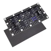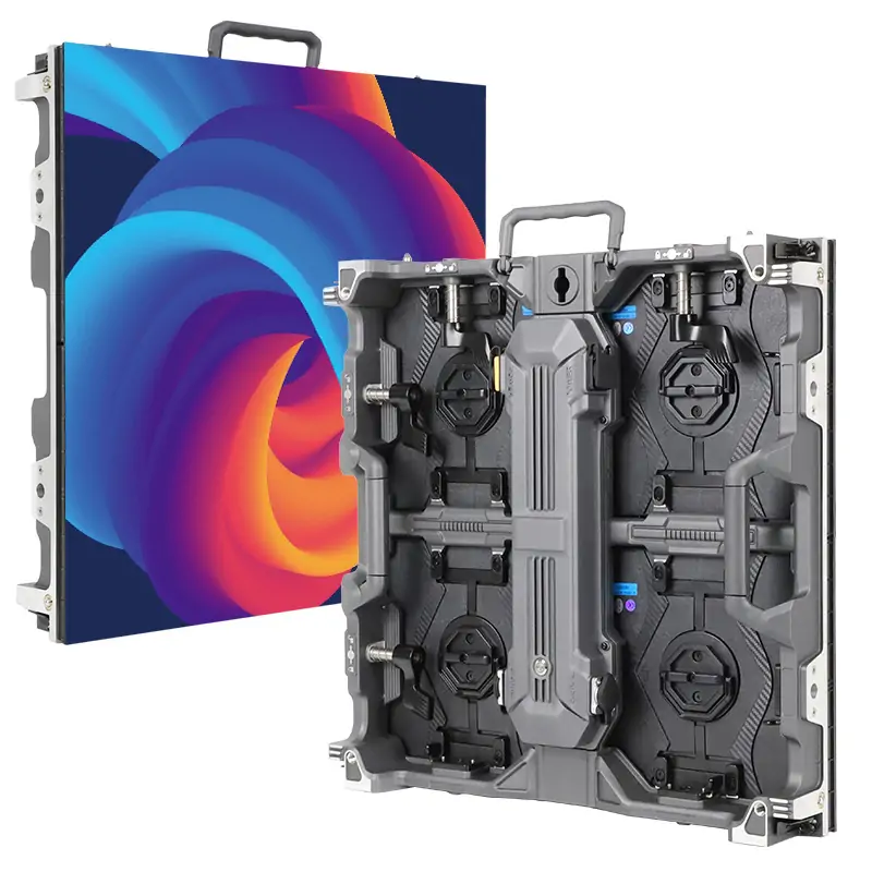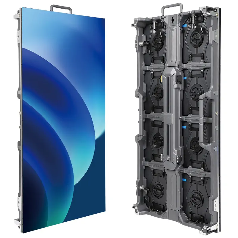
MIP vs SMD vs COB describes three approaches to packaging LEDs for a direct-view video wall. Conventional SMD mounts packaged RGB LEDs on a circuit board; COB mounts bare LED chips directly on the board under a protective coating; MiP packages tiny LED chips before board assembly. Choose by the required pixel pitch, viewing conditions, service plan and total installed cost. No packaging type guarantees the best picture or lowest maintenance cost.
For a fine-pitch LED wall in a boardroom, control room, studio or XR stage, compare actual products at the same resolution and operating brightness. The package is one part of the display system.
This guide compares image quality, durability, repairability, cost and application fit. It covers RGB direct-view displays, rather than LED lighting strips or LCD backlights. Numerical product examples are identified as manufacturer specifications; project scenarios are illustrative.
1. MIP vs SMD vs COB: What Each Technology is
1.1 SMD — Surface-Mount Device
SMD means surface-mount device. In a conventional RGB display, red, green and blue dies sit inside a package that is soldered to the PCB using surface-mount technology (SMT). A common three-in-one package forms one pixel, although multi-pixel packages also exist. Package dimensions vary with the design; they are not universally 2–5 mm.
SMD is an established option for indoor displays and rental systems. Select the actual pitch and package size from the product specification. Component replacement may be possible with suitable equipment and trained technicians, but repair time and access depend on the module. At finer pitches, handling, soldering and calibration become more demanding.
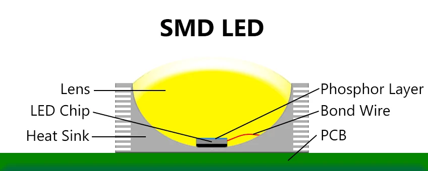
Diagram note: the retained illustration below shows a lighting-style SMD LED with a lens, phosphor layer, LED chip, bond wire, heat sink and PCB. It is a simplified package illustration, not the structure of every RGB video-wall pixel.
1.2 COB — Chip On Board
COB means chip on board. Bare LED dies are attached directly to a substrate and protected with an encapsulating layer. COB can use different electrical connection methods: modern flip-chip COB does not require the wire bonds shown in older designs. For a verified example, see Absen’s flip-chip COB product description.
A continuous coating can protect the display face and change its surface appearance, but the underlying image still consists of discrete pixels. Pitch, surface reflectance, calibration and cabinet alignment affect the result. Protection ratings, brightness and service procedures must be checked for the chosen model; COB does not automatically mean waterproof or maintenance-free.
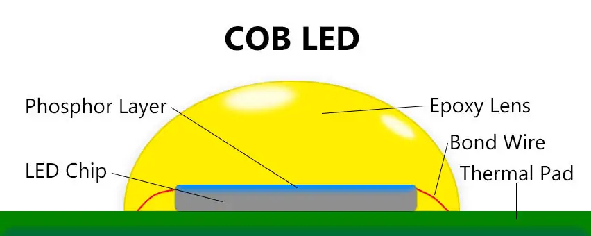
Diagram note: the retained COB lighting illustration labels an LED chip, phosphor layer, epoxy lens, bond wire and thermal pad. RGB flip-chip display modules use a different construction and need no phosphor layer to mix red, green and blue light.
1.3 MIP — Mini/Micro LED in Package
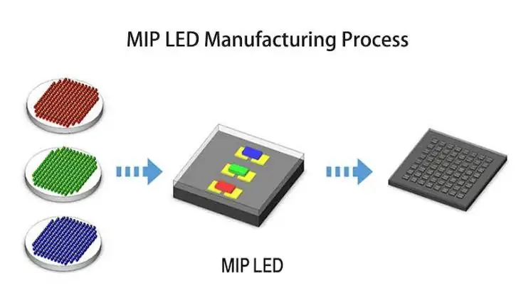
MiP, also written MIP, means Mini/Micro LED in Package in Nationstar’s manufacturing description. Its process forms packaged devices from tiny LED chips, then tests and sorts them before SMT assembly. Devices can contain one pixel or multiple pixels; terminology and implementation vary by supplier.
MiP is not limited to P0.2–P0.6. Nationstar’s cited example covers P0.6–P1.2. Package testing and binning help manufacturers manage defective devices before assembly, but do not guarantee a particular finished-screen failure rate. Ask whether quoted resolution represents native physical pixels or a dynamic-pixel technique.
Process diagram in words: red, green and blue LED chips are combined into a MiP device, then assembled into a display module. Package-level rework depends on the supplier’s tools, coating and approved service process; it is not necessarily a quick on-site repair.
2. MIP vs SMD vs COB: Head-to-Head Comparison
| Feature | SMD | COB | MIP |
|---|---|---|---|
| Pixel pitch | Check model; broad available range | Check model; overlaps SMD and MiP | Check model; not limited to P0.2–P0.6 |
| Pixel structure | Packaged RGB LEDs on PCB | Bare dies on substrate under coating | Packaged tiny LEDs, then board assembly |
| Static contrast | Model and test conditions determine result | Model and test conditions determine result | Model and test conditions determine result |
| Viewing angle | Check horizontal and vertical specification | Check horizontal and vertical specification | Check horizontal and vertical specification |
| Black uniformity | Package finish and calibration matter | Coating and calibration matter | Package finish and calibration matter |
| Visible pixel structure | Depends on pitch and viewing distance | Still has discrete pixels | Still has discrete pixels |
| Durability | Check package protection and cabinet design | Coating protects face; check IP rating | Check package and module protection |
| Repairability | Component rework or module exchange | Module exchange; specialist repair policy varies | Package rework or module exchange |
| Brightness | Compare at required operating level | Compare at required operating level | Compare at required operating level |
| Relative cost | Obtain matched project quotation | Obtain matched project quotation | Obtain matched project quotation |
| Annual failure rate | Request defined, comparable field data | Request defined, comparable field data | Request defined, comparable field data |
| Manufacturing and supply | Established assembly ecosystem | Supplier and process dependent | Supplier and process dependent |
On small screens, scroll the table horizontally. Comparisons are selection guidance, not guaranteed specifications.
3. MIP vs SMD vs COB: Image Quality at Every Distance
Compare sample panels at the nearest viewing position, using the same content, brightness and room lighting. A fine pixel pitch reduces pixel spacing; packaging alone does not make pixels invisible. All three technologies can show pixel structure when viewed closely enough.
Test small text, diagonal lines, skin tones, low-gray gradients and dark scenes. Look for color shifts off-axis, reflected room light, module boundaries and differences between replacement modules. A high contrast figure is useful only when the measurement conditions are comparable.
For initial sizing, use the pixel-pitch selection guide, then validate with a sample. On camera, moiré also depends on the camera sensor, lens, focus and framing. ROE Visual’s virtual-production discussion emphasizes pitch and the plane of focus relative to the wall. COB or MiP is not an automatic anti-moiré guarantee.
4. MIP vs SMD vs COB: Durability in the Real World
Durability comes from the whole module and cabinet design, including its coating, connectors, mounting, cooling and handling protection.
Exposed SMD packages can be damaged during handling. Protective treatments and edge guards can reduce that risk, so compare the supplied configuration rather than assuming all SMD panels are fragile. Use the manufacturer’s transport cases and handling procedures.
COB encapsulation can protect the front surface, but it does not make the entire cabinet sealed against water. For example, Absen’s KLCOB V2 cutsheet specifies different front and rear protection ratings. Check operating temperature, humidity, cleaning instructions and ventilation for every product.
MiP packages are protected before board assembly, while the finished module may have additional surface treatment. Neither this architecture nor COB establishes a universal annual failure percentage. Request field data with a defined unit—pixels, modules or cabinets—and comparable operating conditions.
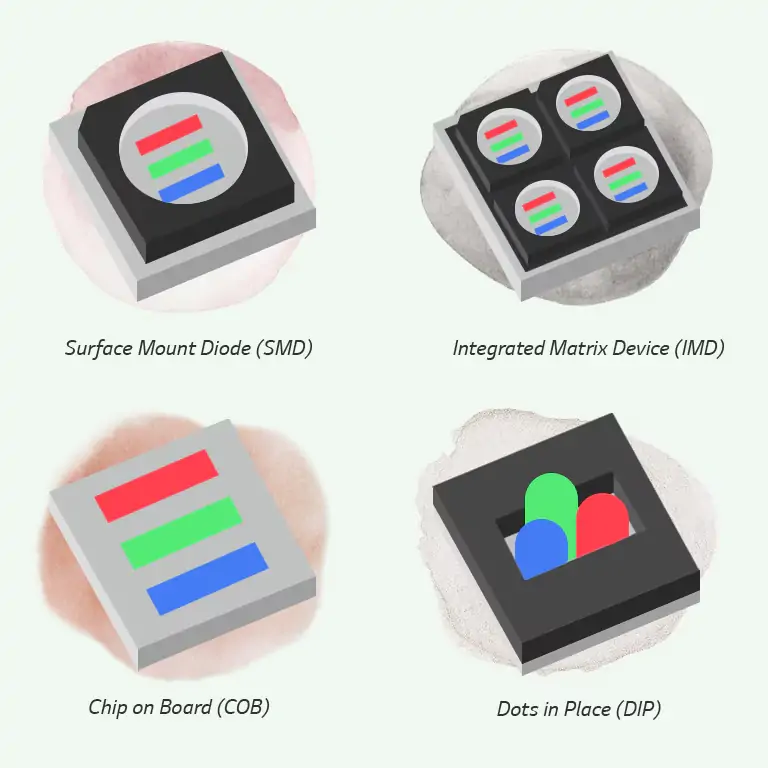
Graphic note: the retained image below compares SMD, integrated matrix device (IMD), COB and DIP, rather than three MiP variants. It shows one RGB package, a multi-pixel package, directly mounted dies and separate through-hole lamps. Its “Dots in Place” label is incorrect: DIP means dual in-line package; see the DIP vs SMD explanation.
5. MIP vs SMD vs COB: What Happens When a Pixel Dies
Plan for a failed pixel or module before purchase. Distinguish restoring the wall by swapping a module from repairing the faulty component later at a service bench.
| Service factor | SMD | COB | MIP |
|---|---|---|---|
| Fix method | Package rework or module swap | Module swap; ask about depot repair | Package rework or module swap |
| Part cost | Request model-specific quotation | Request model-specific quotation | Request model-specific quotation |
| Labor | Access, tools and calibration determine time | Access and calibration determine swap time | Access, tools and calibration determine time |
| Skill level | Trained service technician for rework | Approved procedure for module exchange | Trained service technician for rework |
| Parts availability | Match package, batch and calibration | Match module and calibration | Match package/module and calibration |
On small screens, scroll the table horizontally. Comparisons are selection guidance, not guaranteed specifications.
For any technology, a stocked, calibrated replacement module can be more practical during operation than microscopic component rework. Ask who is authorized to repair the module, whether coating must be restored and how replacement parts are color-matched. Warranty terms may limit field repairs.
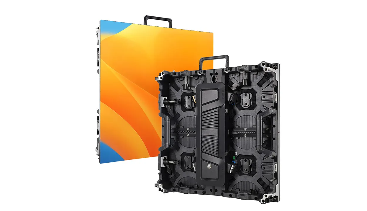
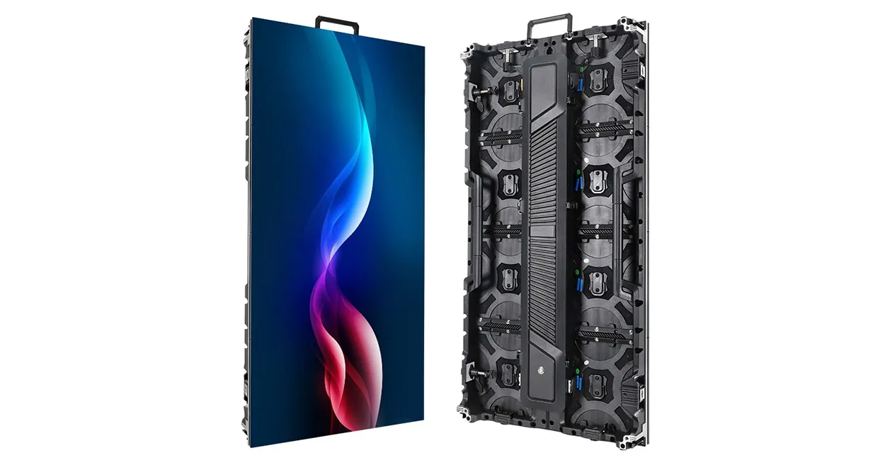
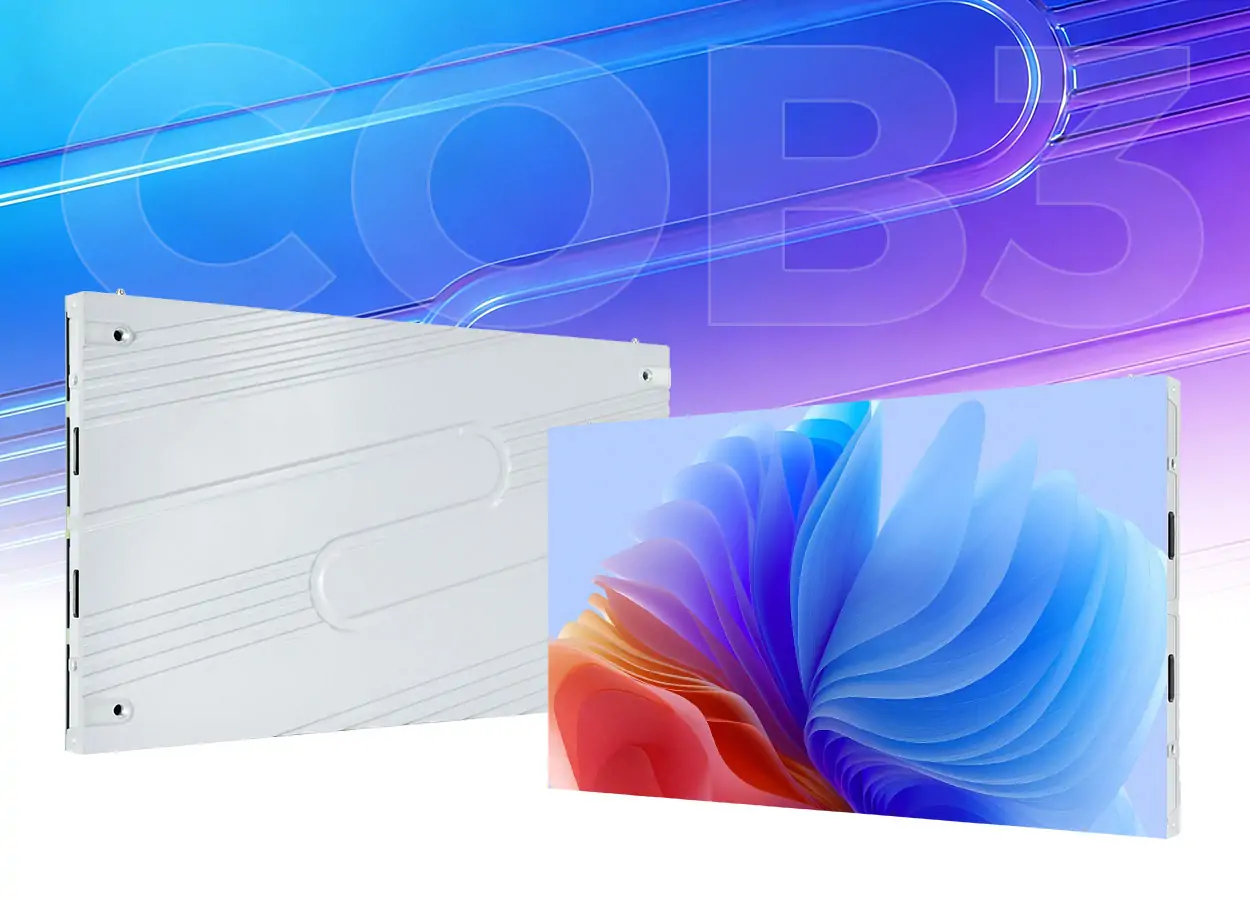
The EA600COB3 COB display, for example, provides front access and replaceable modules. That is a service feature of this product, not proof that every COB wall takes longer to repair. Compare a five-year ownership budget including spare modules, labor, shipping, calibration and downtime. Avoid calculations that mix a pixel failure percentage with a price per module.
6. MIP vs SMD vs COB: Where They Came From and Where They’re Going
These approaches developed along overlapping paths, rather than a simple sequence in which each makes the previous one obsolete.
Conventional SMD benefits from established surface-mount assembly and a broad supplier base. As pixel density increases, package dimensions, placement accuracy and handling become more important. A mature process can still meet a demanding project brief.
COB moves chip attachment and protection onto the module substrate. Flip-chip implementations provide another construction option, while surface treatments and manufacturing processes continue to vary. Buyers should evaluate the finished display and its service support.
MiP puts testing and packaging ahead of final board assembly and can use SMT equipment downstream. That compatibility is useful for manufacturing, but does not establish the installed price, repair speed or future resale value of a wall.
For a display intended to remain in service through 2030, obtain a written support period, spare-part policy and calibration procedure. Do not base the purchase on predicted price declines or a claim that one package will inevitably replace the others. The retained video provides additional visual context; confirm current specifications with the supplier.
7. MIP vs SMD vs COB: a Real-World Decision Walkthrough
Illustrative scenario: a studio is considering a fine-pitch wall near P0.9, with cameras about 2 meters away and operation for 12 hours a day, six days a week. The EA600COB3 product range includes P0.93, but suitability still requires a studio test. These are planning assumptions, not a completed installation or quotation.
First filter: image testing. Test shortlisted SMD, COB or MiP products with the actual cameras, lenses, shutter settings and intended shots. Record moiré, scan artifacts, reflections and low-brightness color performance. A 2-meter camera distance alone cannot eliminate SMD or certify COB.
Second filter: service. Demonstrate a module replacement with the proposed mounting system. Confirm access, calibration time, backup signal paths and the response-time agreement. Decide how many spares to hold using the supplier’s recommendation and acceptable downtime, rather than assuming a universal 15-minute fix.
Third filter: comparable quotations. Match native resolution, brightness, processor, installation scope, warranty and spare stock. A claimed percentage premium between packaging types is not a substitute for project quotations.
Example decision: choose a COB model if it passes the camera tests and its service package and installed price best meet the brief. Choose another technology if its measured results and support are stronger. This is a conditional purchasing decision, not a claim that COB always wins in broadcast.
Scenario Variable Shift Rules:
- If pitch changes to around P0.6, recheck available COB and MiP models, native resolution and repair procedures.
- If there is no in-house maintenance team, prioritize local support, stocked modules and a demonstrated service workflow.
Core principle: set measurable acceptance criteria for the project, then compare products against them.
8. MIP vs SMD vs COB: Cost at Each Pitch
| Pitch / cost check | SMD | COB | MIP |
|---|---|---|---|
| P1.5 and coarser | Include established SMD options | Quote where protective surface is useful | Check model availability and value |
| Around P0.9–P1.2 | Check actual package and native pitch | Compare installed cost and service | Compare installed cost and service |
| Around P0.6 | Verify a suitable model exists | Confirm yield-related price and spares | Confirm native resolution and spares |
| Below P0.6 | Do not assume availability | Request demonstrated product and support | Request demonstrated product and support |
| All pitches | Match brightness, resolution and scope | Include processor, installation and spares | Include warranty and support costs |
On small screens, scroll the table horizontally. Comparisons are selection guidance, not guaranteed specifications.
The table is a quotation checklist, not a market price list. As pitch shrinks, pixel count rises for the same wall area, but the bill also depends on manufacturing yield, electronics and cabinet design. Request the same deliverables from each supplier. Include processing, structure, installation, freight, tax, spares and service; state the currency, region and quotation date. Use the LED display size calculation guide to keep dimensions and native resolution consistent.
9. MIP vs SMD vs COB by Application
| Application | Options to evaluate | Why |
|---|---|---|
| Conference room (2–4 m viewing) | Shortlist SMD, COB or MiP | Test text size and resolution from the rear seats |
| Boardroom (1–2 m viewing) | Compare fine-pitch products | Test nearest-seat clarity and reflections |
| Broadcast studio | Camera-tested products of any suitable type | Validate lenses, focus, scan behavior and moiré |
| Control room / NOC (24/7) | Models rated for the operating duty | Prioritize legibility, redundancy and service |
| XR virtual production | Products tested with the production system | Validate camera/processor synchronization and shots |
| Luxury retail (close viewing) | Compare fine-pitch and protected-face options | Evaluate finish, lighting and cleaning |
| Rental and staging (indoor) | Serviceable rental cabinets | Prioritize handling protection and spare compatibility |
| Ultra-fine pitch (below P0.6) | Compare demonstrated COB and MiP options | Check physical resolution, availability and repairs |
| High-traffic public (indoor) | Protected-face products | Verify impact protection and cleaning procedure |
On small screens, scroll the table horizontally. Comparisons are selection guidance, not guaranteed specifications.
These application choices are shortlists for evaluation. A rental company may prioritize rugged cabinets and interchangeable spare modules, while a control room may prioritize text readability, redundancy and a support agreement. Both should test the selected product at its normal operating brightness.
Published pitch ranges overlap, and suppliers may offer different package options within one product family. Obtain a current specification and sample for the exact model. Prices and availability can change; no reliable universal cost multiplier or future price forecast applies to SMD, COB and MiP as whole categories.
10. FAQs
11. Conclusion
MIP vs SMD vs COB is a product-selection decision, not a universal ranking. SMD uses packaged LEDs on the board, COB places dies directly on the substrate, and MiP packages tiny LEDs before final assembly. Their usable pitches and performance overlap.
Start with wall size, required native resolution, nearest viewers and camera use. Then compare samples, demonstrated maintenance and quotations with the same scope. Choose the display that meets those requirements with dependable support. A packaging label alone cannot establish visual quality, lifetime or value.
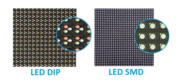 DIP vs SMD LED Display: Which One Fits Your Projects
 How to Choose the Best Giant LED Display for Your Programs
Related Posts

Fill In Your Needs In Detail
Fill in the screen usage scene and size you need in “Content”.You will get a quote.